Low-power voltage reference

a low-power, reference voltage technology, applied in the direction of electric variable regulation, process and machine control, instruments, etc., can solve the problems of high power consumption, many traditional reference voltage circuits cannot meet the low voltage reference requirement, and low power consumption, and achieve the effect of stable valu

Active Publication Date: 2009-07-21
MONOLITHIC POWER SYST
View PDF2 Cites 14 Cited by
  • Summary
  • Abstract
  • Description
  • Claims
  • Application Information

AI Technical Summary

Benefits of technology

[0007]The present invention utilizes the work function difference between gate terminals of an input terminal transistor pair, to generate a predetermined reference voltage, which can be adjustable. The bulk of the reference circuit consists of a transconductance amplifier where its input offset is set to be the same as the magnitude of the reference voltage. This can be done, for example, by using a pair of MOS transistors as the input terminal transistor pair. The gate terminals are made of different types of polysilicon materials. In particular, one of the gate-terminals of the pair of MOS transistors is made of p+ polysilicon material, and the other gate-terminal of the pair of MOS transistors is made of n+ polysilicon material. Transistors with different kinds of gate materials with the same size (aspect ratio) will have different work function values. The circuit according to the present invention amplifies the work function difference between gate terminals of the input terminal transistor pair. Due to the characteristic of work function, the output reference voltage of the circuit in the present invention can maintain a very stable value.

Problems solved by technology

Low power consumption has become one of the main issues in the electronics industry for many product areas such as cellular phones, biomedical implants, digital watches, calculators, tape players, portable computers, LCD driver circuits, in short, all types of portable and battery powered electronic devices.
Many traditional reference voltage circuits cannot meet this low voltage reference requirement.
In some other reference circuits, such as the bandgap reference voltage generator shown in U.S. Pat. No. 4,628,248 by Birrittella et al, the current needed to activate the reference voltage generator results in high power consumption, due to use of bipolar transistors, e.g., IB and VBE.
The bandgap reference voltage generator has the disadvantage of high power consumption.

Method used


Image

  • Low-power voltage reference
  • Low-power voltage reference
  • Low-power voltage reference

Examples


Embodiment Construction

[0014]Embodiments of a system and method that uses a reference voltage generator as a shunt regulator are described in detail herein. In the following description, some specific details, such as example circuits are included to provide a thorough understanding of embodiments of the invention. One skilled in relevant art will recognize, however, that the invention can be practiced without one or more specific details, or with other methods, components, materials, etc.

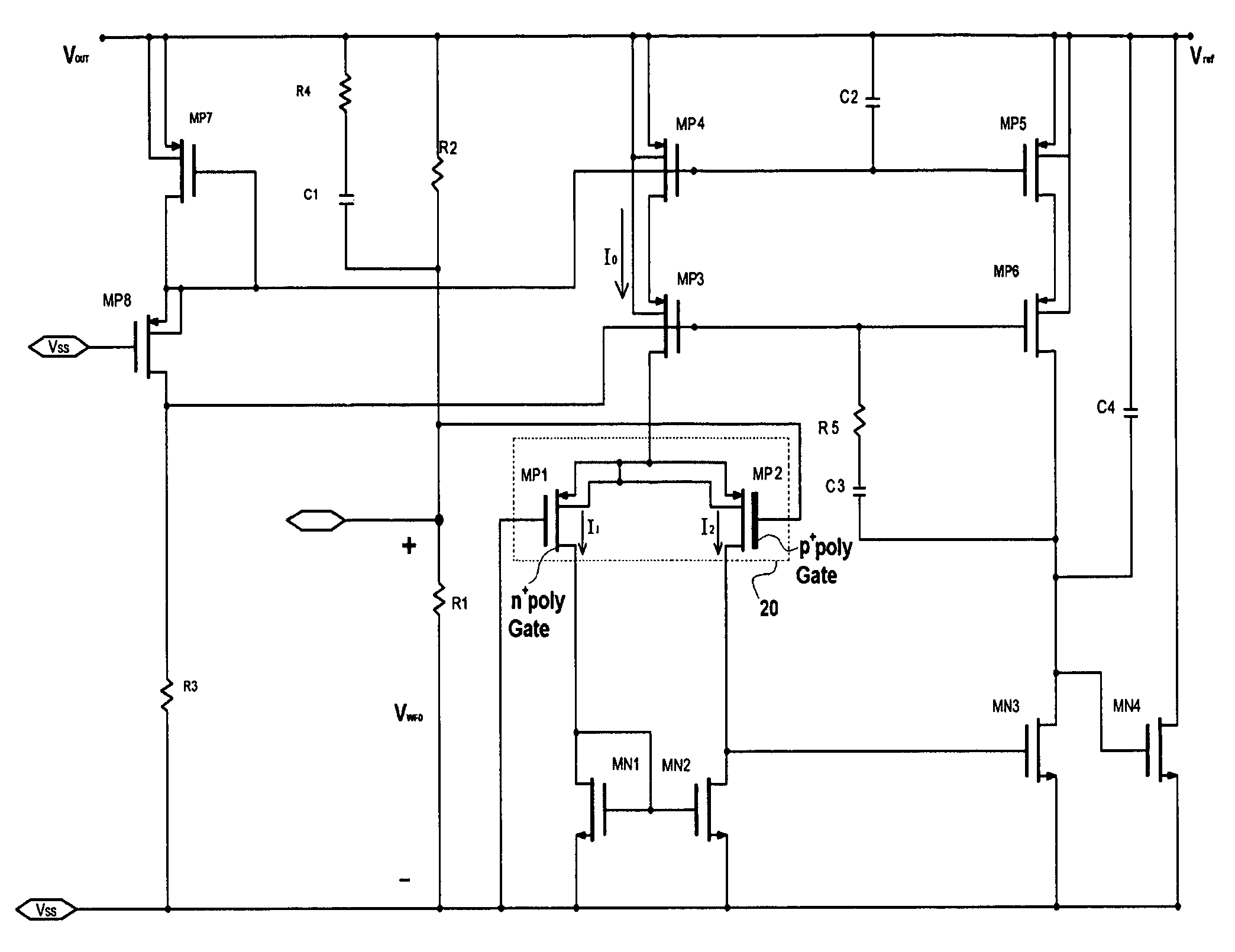
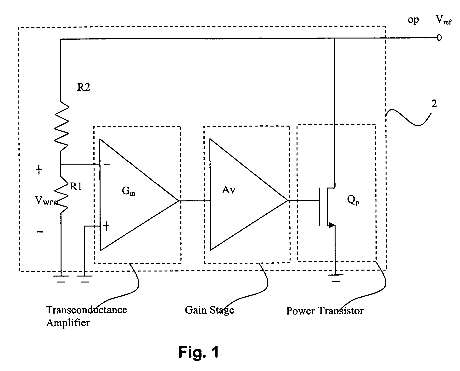
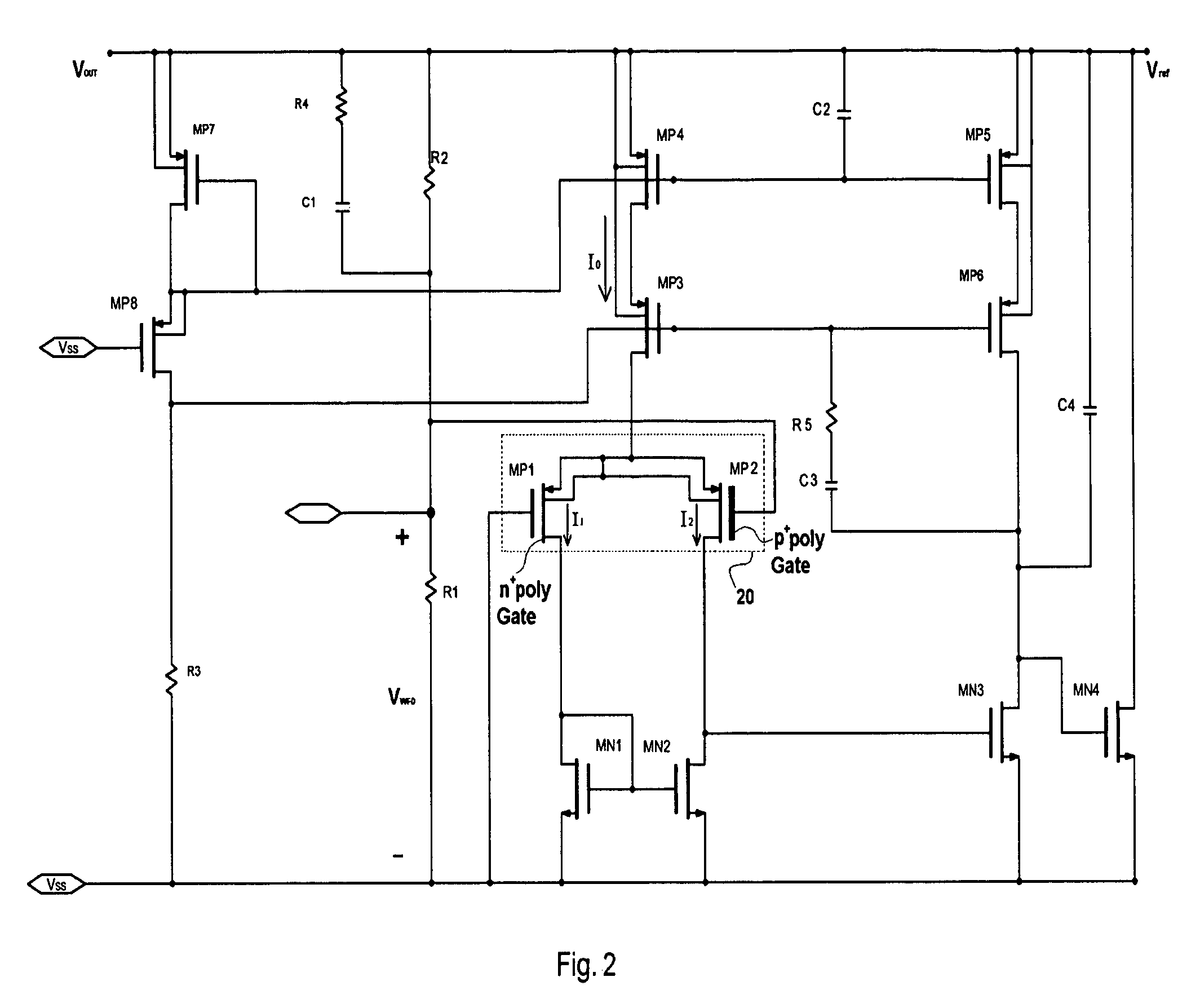
[0015]The invention discloses the configuration of a circuit of a shunt regulator, which is a very low-power reference voltage generator mainly utilizing MOSFETs. The reference circuit includes a transconductance amplifier, where its input offset is set to be the same as the magnitude of the reference voltage. This is done by using a pair of MOS transistors with their gate terminals formed from different kinds of polysilicon materials. The gate-terminal of one transistor of the pair of MOS transistors is made of p+ poly,...


PUM


Abstract

A circuit provides a voltage reference using very low power. It can also be used as a shut regulator for a quiescent current as low as 1.5 μA. It includes a transconductance amplifier, a gain stage, and a power transistor. One embodiment of this invention utilizes a work function difference between p+ gate and n+ gate to generate a predetermined reference voltage. In another embodiment of this invention, the predetermined reference voltage can be pre-adjusted using gate materials with different work functions.

Description

FIELD OF INVENTION[0001]The invention relates to a voltage reference circuit consuming very low power, and more particularly, relates to a reference voltage generator that can operate under very low current supply and simultaneously keep its output voltage constant over variable temperatures.BACKGROUND INFORMATION[0002]Nowadays, many electronic devices are built by connecting together electrical components, ranging from a few electrical components in simple circuits to millions of them in complex circuits. Low power consumption has become one of the main issues in the electronics industry for many product areas such as cellular phones, biomedical implants, digital watches, calculators, tape players, portable computers, LCD driver circuits, in short, all types of portable and battery powered electronic devices.[0003]For example, along with the recent increase in the popularity of portable equipment, the requests for large-scale integrated (LSI) devices performing battery operations a...

Claims


Application Information

Patent Timeline
Patent Type & Authority Patents(United States)
IPC IPC(8): G05F3/16G05F1/613
CPCG05F3/30
Inventor MORAVEJI, FARHOODHSING, MICHAEL
Owner MONOLITHIC POWER SYST
Why Eureka
Try Eureka