Drive mechanism of a printing unit

a printing unit and drive mechanism technology, applied in printing, rotary letterpress machines, lithography, etc., can solve the problems of tooth breakage and reduce printing quality, and achieve the effect of improving printing quality and reducing mechanical outlay for driving the cylinder pair

Inactive Publication Date: 2005-06-07
KOENIG & BAUER AG
View PDF29 Cites 11 Cited by
  • Summary
  • Abstract
  • Description
  • Claims
  • Application Information

AI Technical Summary

Benefits of technology

[0020]A coupling, which is flexible in the axial direction, and which is located between the drive motor and the forme cylinder, is preferably embodied as a torsionally rigid shaft coupling which, however, is flexible or resilient in the axial direction, and is configured for example, as an expansion coupling or as a compensation coupling. The employment of a non-switchable, positively-connected multi-disk coupling is particularly advantageous which coupling, in contrast to other positively-connected couplings, is almost entirely free of play in the circumferential direction, does not require an extensive production outlay and simultaneously makes an axial position

Problems solved by technology

In the prior case, the gear wheel engagement can lead to tooth breakage, or to

Method used


Image

  • Drive mechanism of a printing unit
  • Drive mechanism of a printing unit
  • Drive mechanism of a printing unit

Examples


Embodiment Construction

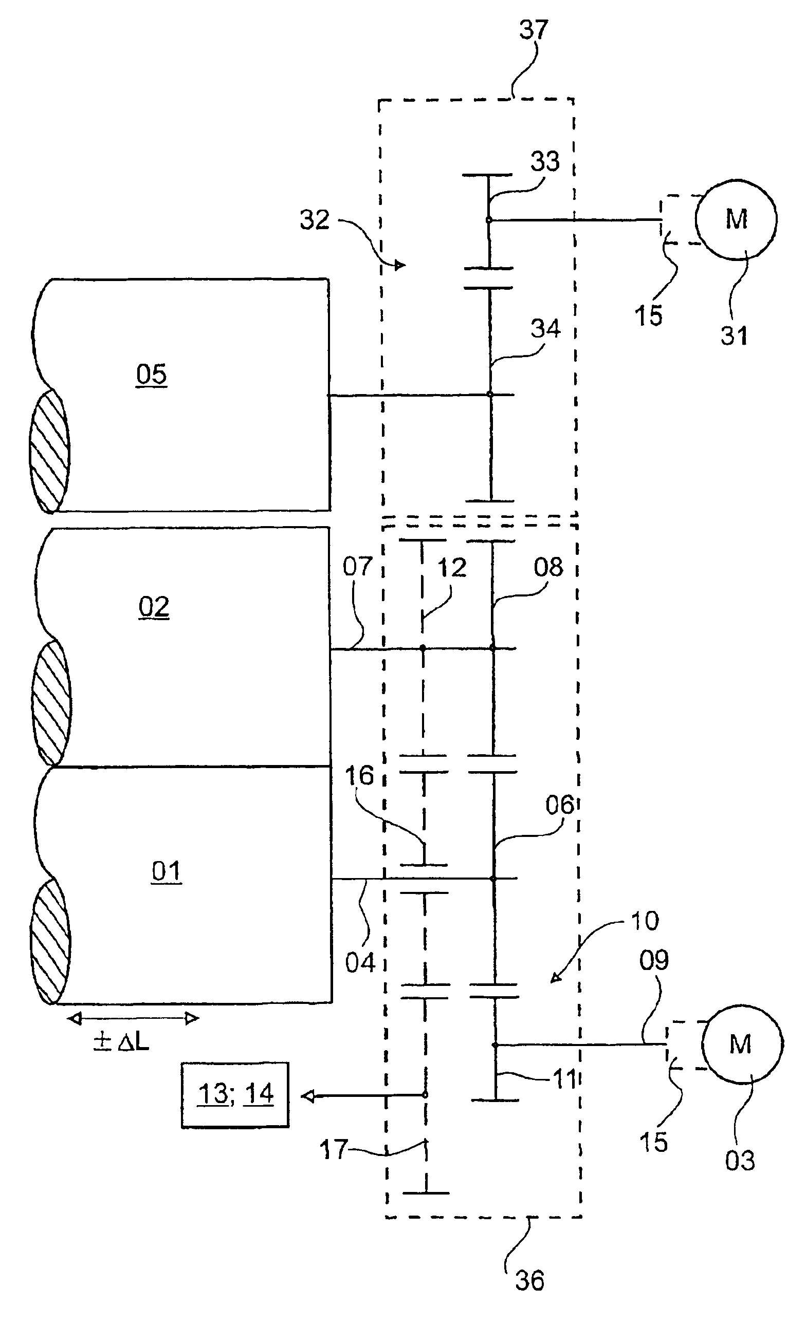
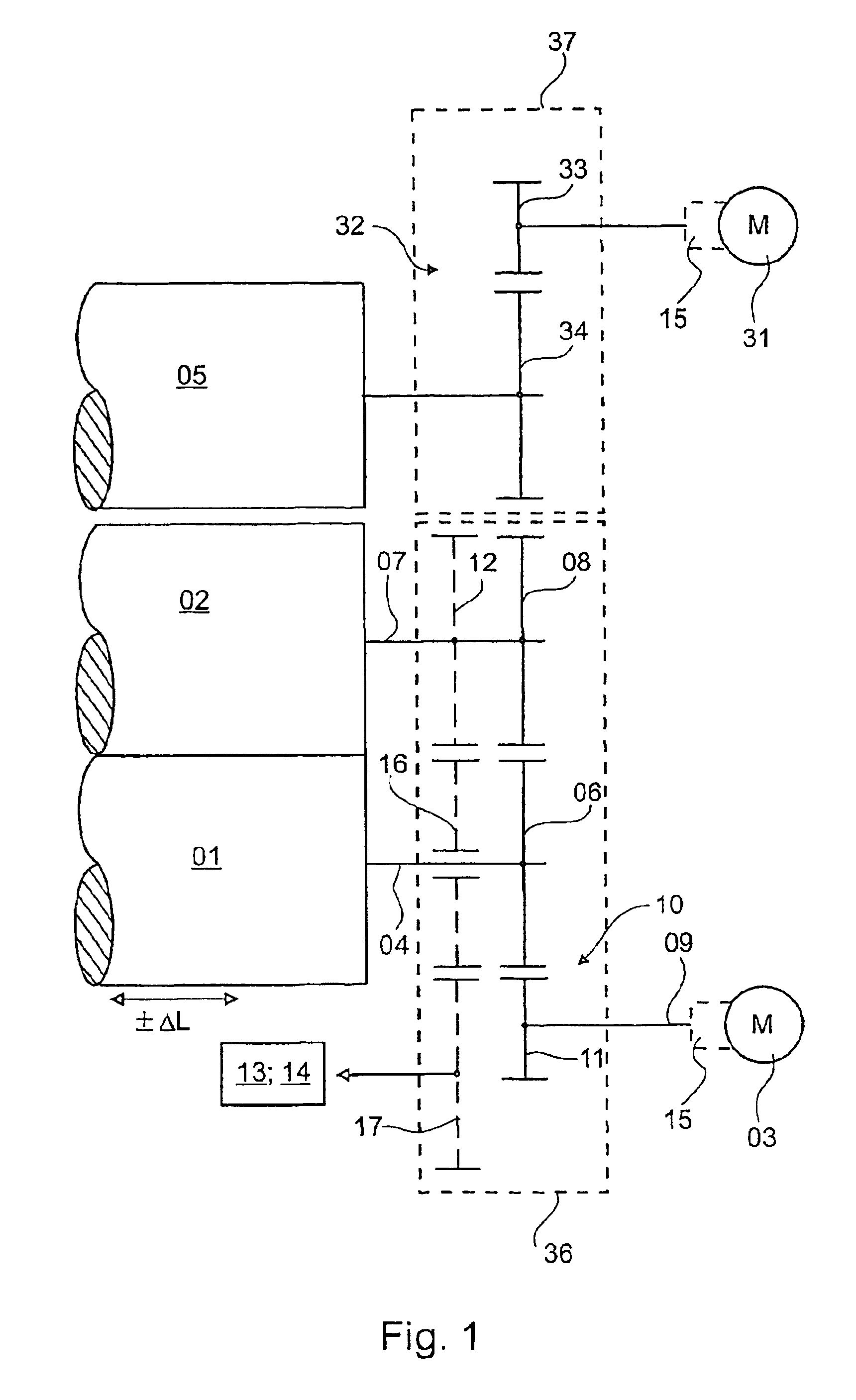
[0032]Referring initially to FIG. 1, there may be seen a first preferred embodiment of a drive mechanism of a printing unit in accordance with the present invention. A printing unit of a printing press has a first cylinder 01, for example a forme cylinder 01, and a second cylinder 02, for example a transfer cylinder 02. The two cylinders 01, 02 can be driven together by the use of a first drive motor 03, which is in operative connection with the forme cylinder 01. The forme cylinder 01, in turn, drives the transfer cylinder 02 via a drive connection. During printing, the transfer cylinder 02 works together with, and forms a printing position with a third cylinder 05 which is only shown schematically in FIG. 1. For example the third cylinder 05 may be a second transfer cylinder 05 of a cooperating printing unit, or a counter-pressure cylinder 05 which does not transfer ink, for example a satellite cylinder 05. The drive mechanism of the third cylinder 05, or that of the cooperating s...


PUM


Abstract

A drive mechanism is provided for a printing unit. The printing unit has an axially movable forme cylinder and a second cylinder that cooperates with the forme cylinder. The forme cylinder can be driven by a drive motor through a spur tooth gear. The second cylinder is driven by the forme cylinder through a drive connection between the two.

Description

FIELD OF THE INVENTION[0001]The present invention is directed to a drive mechanism for a printing unit. The printing unit has at least two cylinders, at least one of which may be axially movable. The two are driven by a common drive motor.BACKGROUND OF THE INVENTION[0002]A printing group with forme and transfer cylinders driven in pairs is known from DE 44 30 693 A1. The forme cylinder is driven and its output is transmitted to the transfer cylinder via spur wheels. A journal of the forme cylinder, embodied as a rotor, is axially displaceable in the stator for adjusting the lateral register on the forme cylinder.[0003]EP 0 644 048 B1 discloses cylinders which are driven while coupled in pairs. The possibility of coupling an associated inking system with the driving connection of the pair is mentioned. In a schematic representation, the transfer cylinder is driven by the drive motor, and power is transferred from the transfer cylinder to the forme cylinder, and from the forme cylinde...

Claims


Application Information

Patent Timeline
IPC IPC(8): B41F13/008B41F31/00B41F31/15
CPCB41F13/008B41F31/004B41F31/15B41P2200/20B41P2213/20B41P2213/202B41P2213/206B41P2213/90
Inventor MASUCH, BERND KURT
Owner KOENIG & BAUER AG
Why Eureka
Try Eureka