
Low impact gas spring

a gas spring and low impact technology, applied in the field of gas springs, can solve the problems of increasing the maintenance and repair cost of the press, increasing the need for press maintenance, and impulsing or load spikes of relatively high magnitude and short duration, so as to reduce the impact force, reduce the load, and reduce the load

Active Publication Date: 2009-07-14
DIEBOLT INT
View PDF11 Cites 22 Cited by
  • Summary
  • Abstract
  • Description
  • Claims
  • Application Information

AI Technical Summary

Benefits of technology

"The gas spring in this patent provides a smooth and gradual load distribution between parts of a machine, such as a press. It reduces the force required to displace the piston rod assembly, minimizes impact force on the press, reduces spike loads, extends the useful life of the press, reduces noise, is durable, reliable, economical, and has a long life in use."

Problems solved by technology

In addition, since the mechanical drive mechanism of the press typically has already begun moving and accelerating the ram and the die half attached thereto before it begins to actuate and overcome the resistance produced by the gas springs, the initial impact or actuation of the gas springs creates an impulse or load spike of relatively high magnitude and short duration on the drive mechanism of the drive press.
The load spikes can cause an increase in the necessary press maintenance, thereby increasing the maintenance and repair costs of the press.
In some instances, the spike loads may damage the drive mechanism of the press, thereby decreasing the useful life of the press.
As such, the drive mechanism is subjected to further impulse or load spikes that can result in damage to the press or formed part, for example, by causing vibration.

Method used


Image

  • Low impact gas spring
  • Low impact gas spring
  • Low impact gas spring

Examples


Embodiment Construction

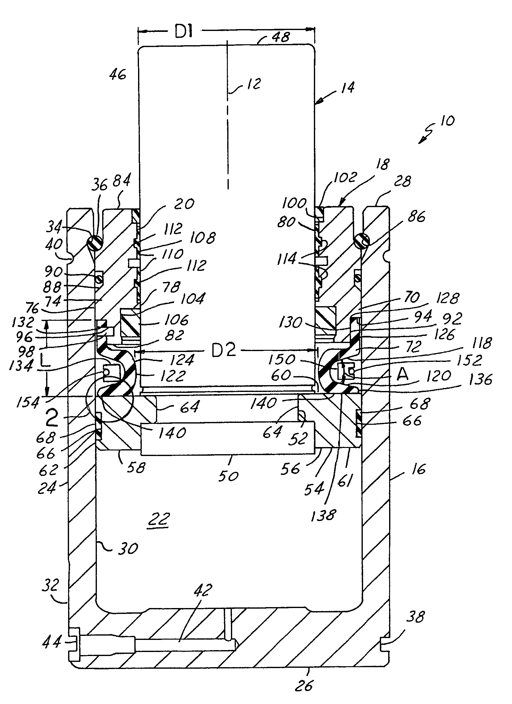
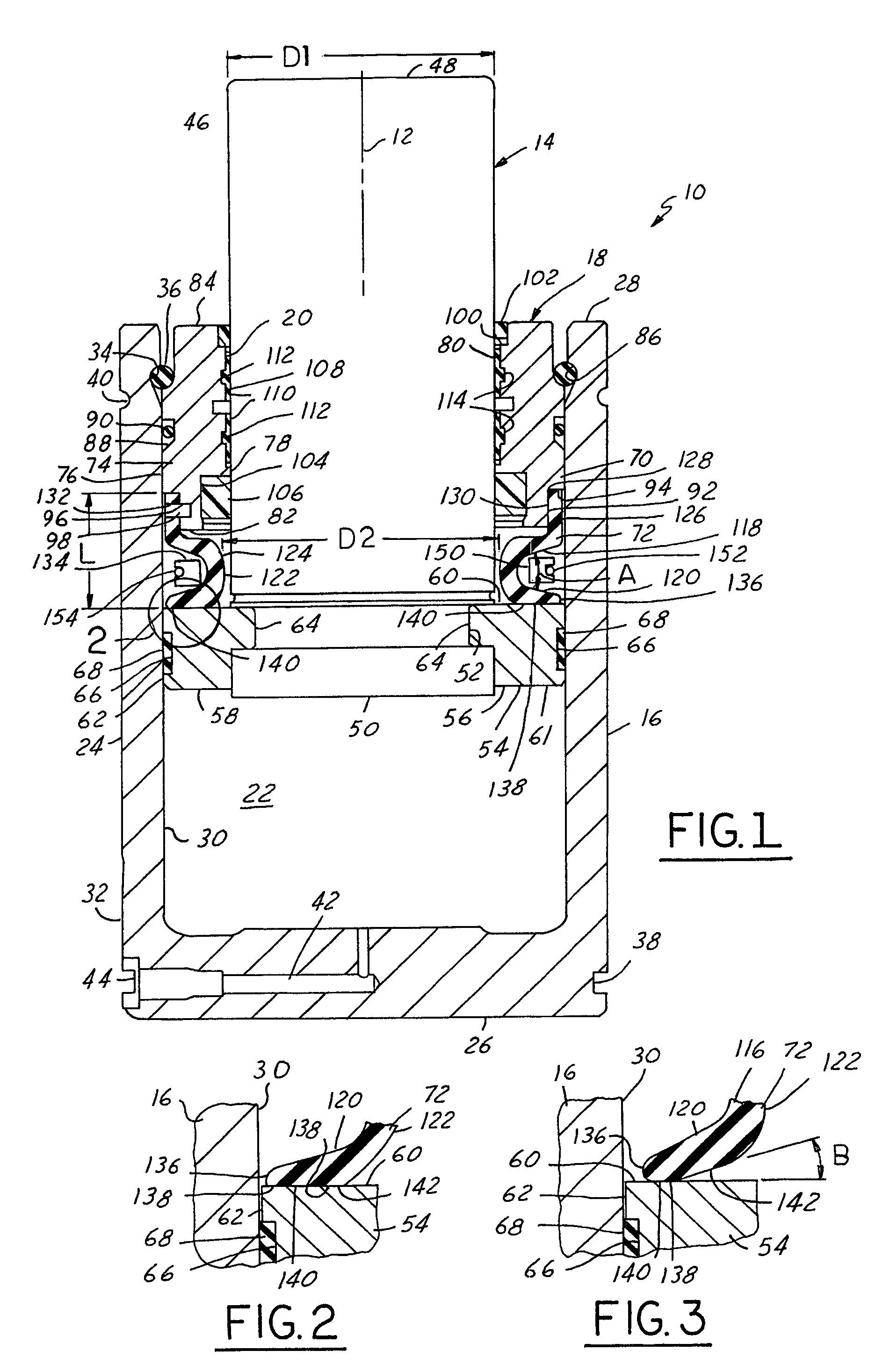
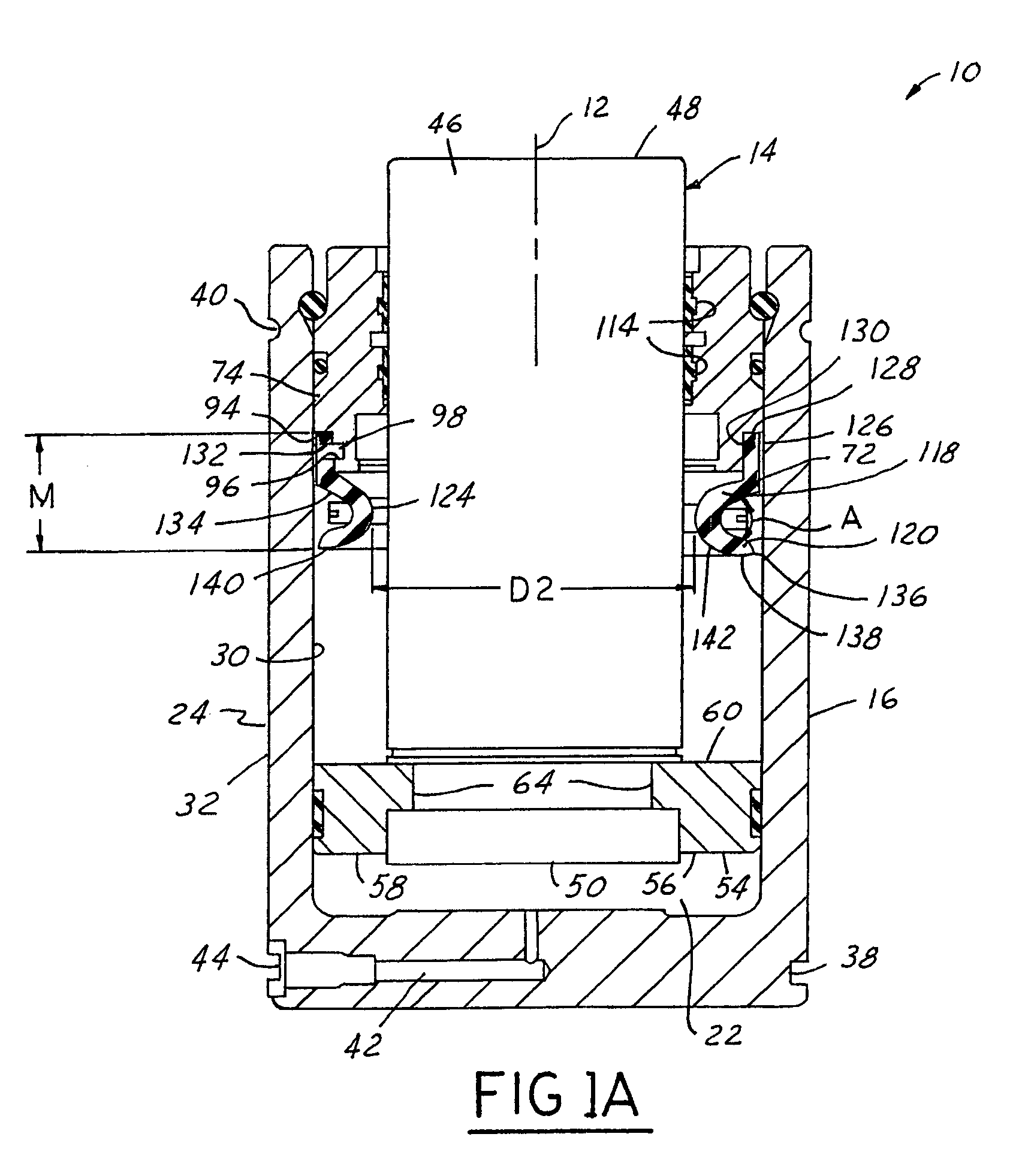
[0019]Referring in more detail to the drawings, FIG. 1 illustrates one presently preferred embodiment of a gas spring 10, such as those used in mechanical presses (not shown). Generally, a plurality of gas springs 10 may be disposed in the mechanical press such that a piston rod assembly 14 of each gas spring 10 is engaged and driven by a ram of the press as the ram advances to form a sheet metal blank in a die assembly of the press. The press may be an eccentric, crank or toggle type mechanical press, for example. Desirably, the force applied to the press ram upon initially moving the piston rod assembly 14 from its extended position toward its retracted position, and also when the press ram is disengaging the piston rod assembly 14 on a return stroke, is reduced. Accordingly, the gas spring 10 reduces the impact force on the press, both during the forming and return strokes of the press, and reduces vibration and noise in operation, thereby enhancing the ability to produce a unifo...


PUM


Abstract

A gas spring for providing a smooth and generally gradual load distribution between interrelated parts of a press has a casing defining at least in part a gas chamber. A housing is received at least in part in the casing. The housing has a through bore sized for receipt of the piston rod therein for reciprocation between extended and retracted positions. A piston retainer is attached for conjoint movement with the piston rod. An end of the housing flexes between a compressed position when the piston retainer abuts the housing as the piston rod moves toward its extended position and an uncompressed position when the piston retainer moves toward its retracted position and out of engagement with the housing.

Description

REFERENCE TO RELATED APPLICATION[0001]Applicant claims the benefit of provisional application, Ser. No. 60 / 602,777 filed Aug. 19, 2004.FIELD OF THE INVENTION[0002]This invention relates generally to gas springs, and more particularly to a gas spring constructed to reduce the impact force on a press during at least a portion of the stroke of the gas spring.BACKGROUND OF THE INVENTION[0003]Gas springs are well known and have been used in dies of presses for sheet metal stamping operations. Conventional gas springs have a gas chamber which receives a pressurized gas that provides a force on a piston and a piston rod of the gas spring to bias them to an extended position. The pressurized gas resists the movement of the piston and the piston rod from their extended position to a retracted position. Various housings and seals are provided in the gas spring to retain the piston and piston rod within a casing of the gas spring and to prevent leakage of the pressurized gas from the gas chamb...

Claims


Application Information

Patent Timeline
Patent Type & Authority Patents(United States)
IPC IPC(8): F16F5/00F16F9/02F16F9/58
CPCF16F9/585F16F9/0218F16F9/00F16F9/02F16F9/06F16F9/088
Inventor COTTER, JONATHAN P.
Owner DIEBOLT INT
Learn More