
Sector for vacuum rotating filters and similars

Inactive Publication Date: 2009-07-07
CASFIL IND E COMERCIO
View PDF4 Cites 3 Cited by
  • Summary
  • Abstract
  • Description
  • Claims
  • Application Information

AI Technical Summary

Benefits of technology

[0018]Thus, the present patent has been designed aiming at obtaining a utensil with less number of possible parts, conveniently configured and arranged to allow that the thin permeable filtering sector, manufactured in plastic material, perform its functions with incomparable efficiency and versatility, without the inconvenient already mentioned.
[0020]Its innovating format allows the obtaining of an excellent level of functionality, offering a model of thin permeable filtering sector, which has high durability, having being created, mainly, for lessening the number of stoppages for maintenance or exchange of filtering sectors and filtering fabrics covered in it, avoiding the retention of a wide stock of replacement parts, at the same time, manpower costs are optimized.
[0025]The insert, placed in a strategic position, has the function of avoiding abrasion in that place and guides the percolate liquid through galleries of the grating element into the semi-tubular segment, which in turn forwards the same liquid into the tubular axle of the filtered liquid collection.
[0026]It is understood that this way, the referred device is extremely simple in its construction, being, however, of easy feasibility, however, excellent practical and functional results are kept, offering an innovating constructiveness on the known models.

Problems solved by technology

This way, such devices work in a continuous way and perform the filtering with efficiency, however, there are some drawbacks in relation to the limited durability of the thin filtering sectors, when they are used to separate very abrasive solid materials.
Concurrently to that, there is the perimeter wearing out, for instance, by the fact that it deals with an area of folding the permeable parts and, consequently, more susceptible to the hydrostatic and mechanical pressure of the solid material particles to be retained.
Other limitation is owing to the wearing out of parts of the internal lap disposed in the vertex of the thin filtering sectors and from the separator between the parts, owing to the constant traffic of abrasive powdery material which is carried together with the filtered liquid, causing the rupture of the nozzle at the filtering time, or the separator's rupture, which is outstood from the central portion, going toward the filtered liquid output.
Yet, another inconvenient which is observed in the thin filtering sectors is the loss of filtering area owing to the formation of an impermeable film from the splice of the thin filtering sectors.

Method used


Image

  • Sector for vacuum rotating filters and similars
  • Sector for vacuum rotating filters and similars
  • Sector for vacuum rotating filters and similars

Examples


Embodiment Construction

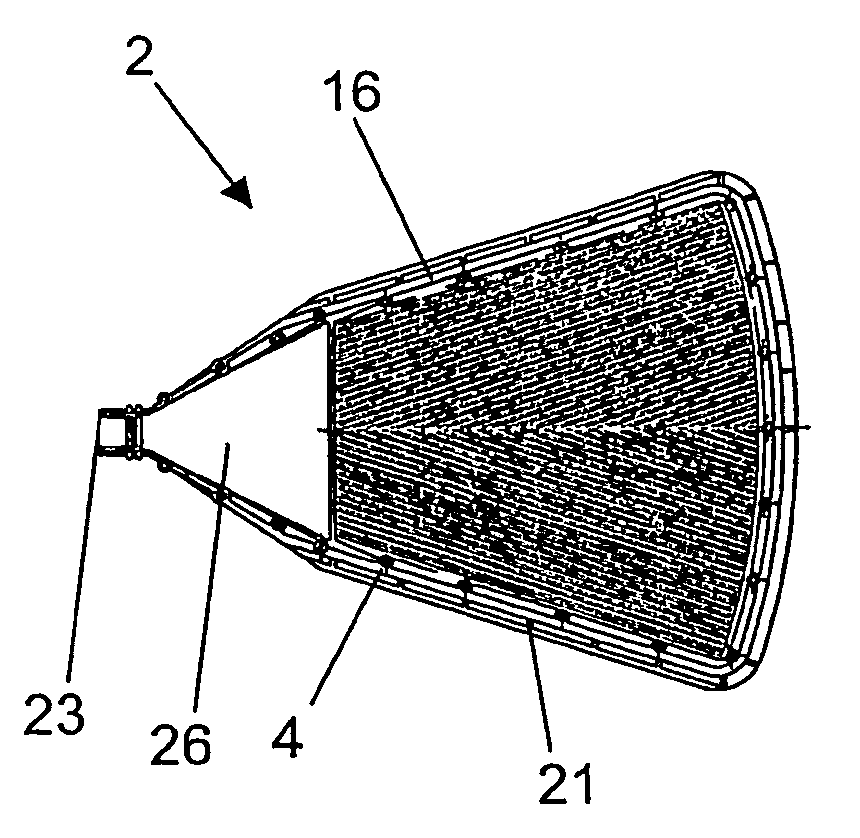
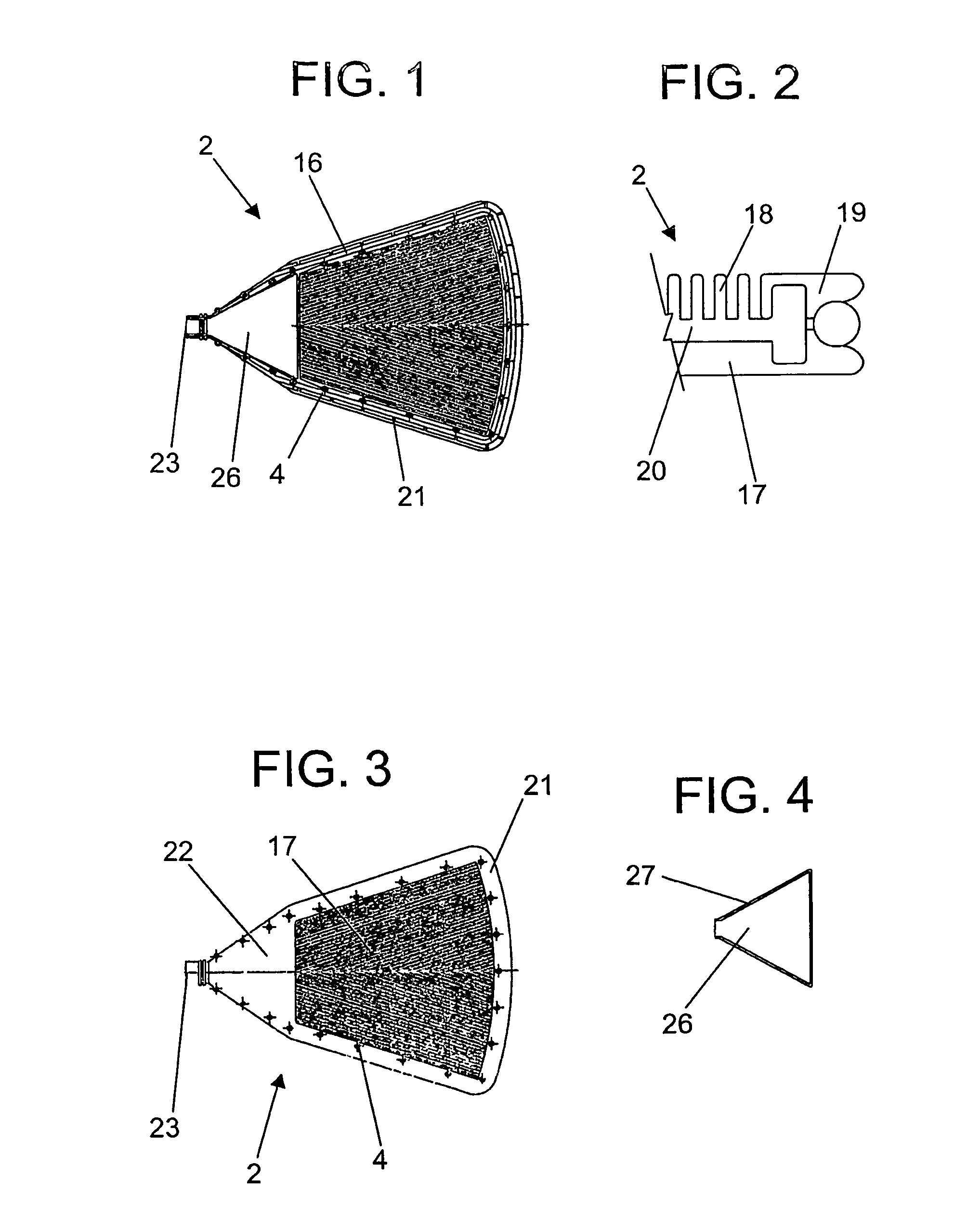
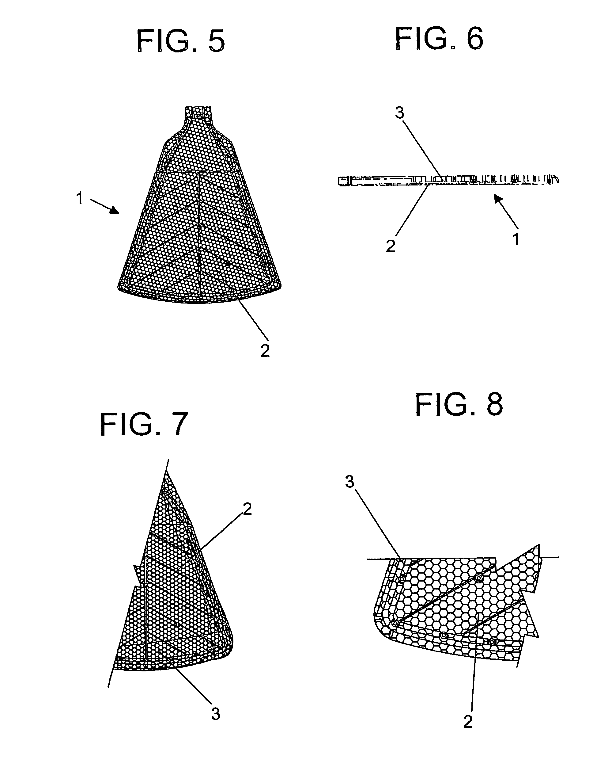
[0048]In compliance with the illustration of figures above listed, the “SECTOR FOR VACUUM ROTATING FILTERS AND SIMILARS”, object of the present patent, is characterized essentially because it deals with filtering sector (1) constituted of two grating elements (2), preferentially of a polymeric material high resistant to abrasion of mining products finely disperse in the filtrate drained through the bi-foliar permeable film element (3), which covers the grating elements (2).

[0049]The grating elements (2) are provided with lowered cylindrical holes (4) distributed along its extension, by where they are united among themselves through self-locking pins (5), constituted of a perforated cylindrical base (6) and internally lowered, from where a perforated (7) cylindrical body of smaller diameter is raised, being that the lower perimeter contains four reinforced saliencies (8) and the upper portion provided with a conic ring (9) and split longitudinally in four quadrants by means of splits...


PUM

PropertyMeasurementUnit
Electrical resistanceaaaaaaaaaa

Abstract

A filtering sector (1) provided with two generating elements (2), obtained preferentially of polymeric material highly resistant to abrasion of mining products finely dispersed in the liquid filtrate, drained through the bi-foliar permeable film element (3), which covers the two grating elements (2), which are provided with lowered cylindrical holes (4) distributed along its extension, a par of grating elements (2) this one united through self-locking pins (5) which receives internally, through its frontal end, a locking counter-pin (11). Each grating element (2) formed by perimeter element (16) has a large edge (21) and, in the internal funneling of the grating elements (2), inserts (26), preferentially elastomeric or polymeric of high resistance to abrasion of the minerals finely disperse in the drained filtrate.

Description

BACKGROUND OF THE INVENTION[0001]The present invention is related to the enhancement of the film filtering sector, formed mainly by two semi-circular trapezium permeable overlapped and united perimetrally and internally parts provided in its vertex with a collecting cylindrical tube, which is coupled in the internal central axis of a cylindrical body integrating a vacuum rotating filter, belonging to the mechanical field, and to which it was given constructive original arrangement, aiming at enhancing its use and performance in relation to other models usually found in the market.[0002]There is, therefore, within the referred patent request, a component especially designed and developed to obtain enormous practice providing great advantages in both, in its use as well as its durability of the filtering sectors.[0003]It is yet, objective of the present request, to present an improvement of the filtering sector of the rotating filters with low costs to its industrial feasibility, howe...

Claims


Application Information

Patent Timeline
IPC IPC(8): B01D33/23F16B19/10
CPCB01D33/23F16B19/1081
Inventor LOVIZZARO, PAULO EDUARDO VASQUEZ
Owner CASFIL IND E COMERCIO
Learn More