Thin film bulk acoustic wave resonator and filter, and radio frequency module using them
a resonator and filter technology, applied in piezoelectric/electrostrictive/magnetostrictive devices, piezoelectric/electrostriction/magnetostriction machines, electrical apparatus, etc., can solve the problems of difficult or impossible to design a band-pass filter, difficult or impossible to achieve compatibility with semiconductor processes, and increase in cost. , to achieve the effect of reducing the element area, wide pass, and low insertion loss
- Summary
- Abstract
- Description
- Claims
- Application Information
AI Technical Summary
Benefits of technology
Problems solved by technology
Method used
Image
Examples
embodiment 1
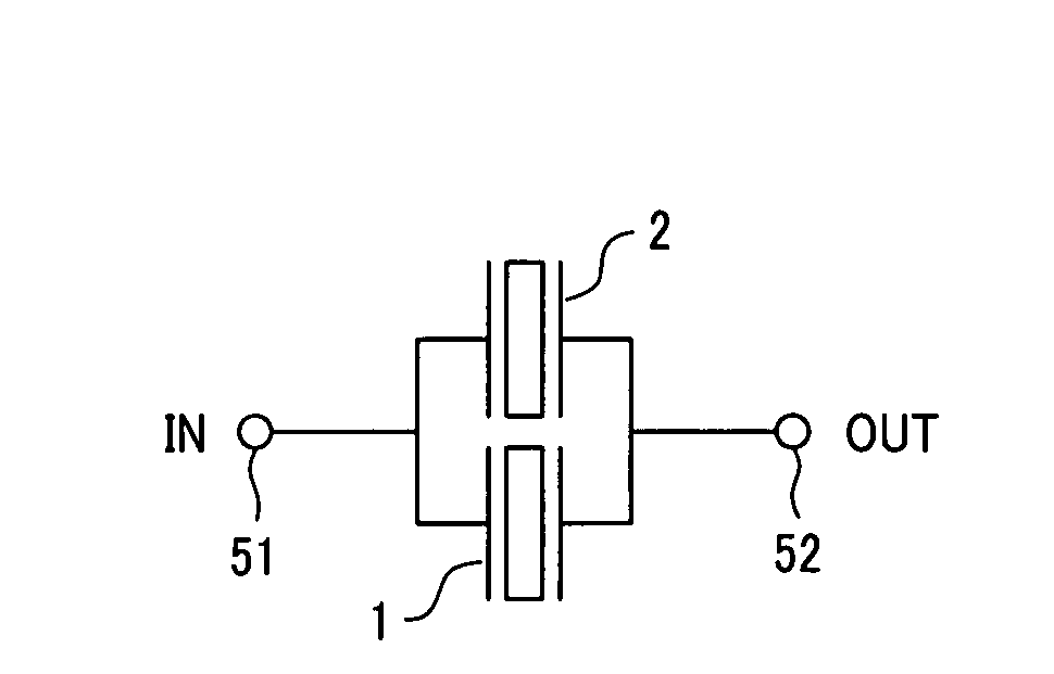
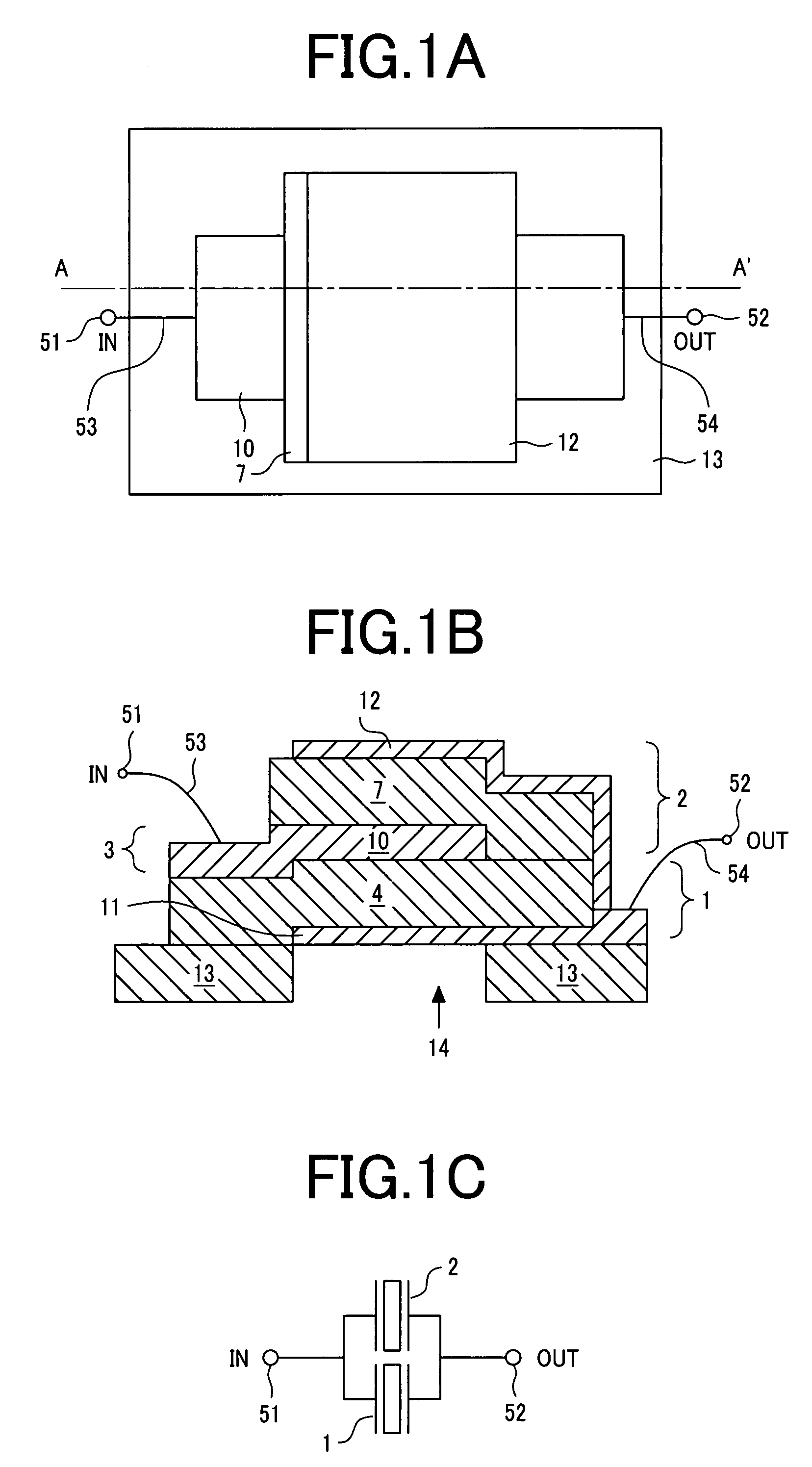
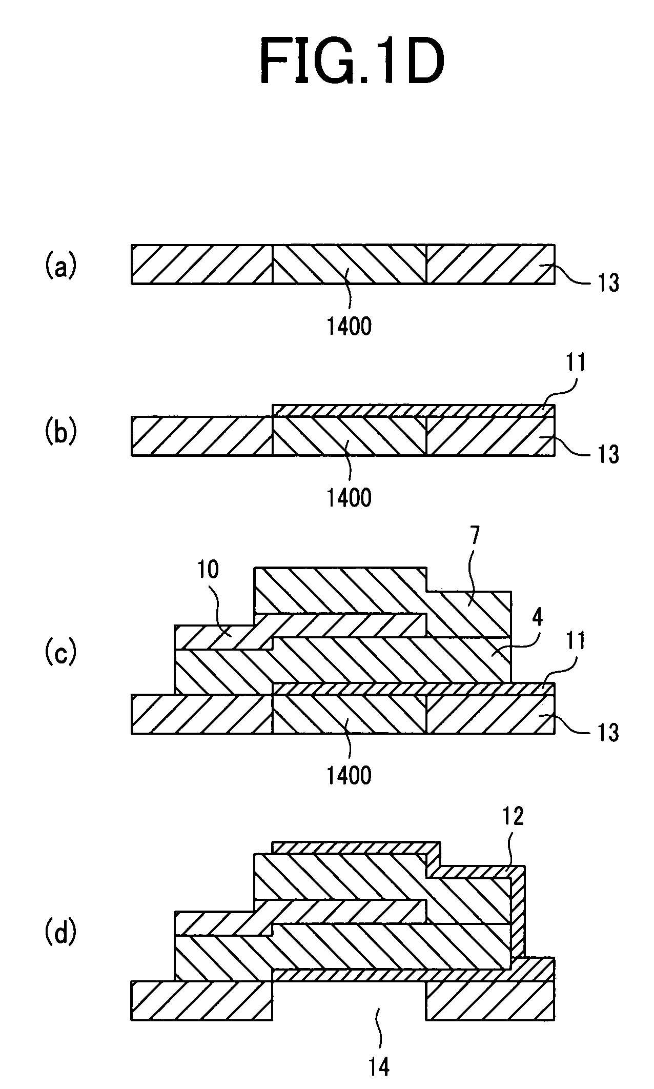
[0055]First, a first preferred embodiment of the invention will be described with reference to FIG. 1A to FIG. 1D, FIG. 2, and FIG. 3. FIG. 1A to FIG. 1C show a BAW resonator structure, which is one embodiment of the invention, wherein FIG. 1A shows a plan view of the resonator structure; FIG. 1B, an A-A′ section view of FIG. 1A; and FIG. 1C, an equivalent circuit to the structure shown in FIG. 1A and FIG. 1B.
[0056]The BAW resonator structure of this embodiment is provided with a first BAW resonator 1, an electroconductive acoustic reflection layer 3, a second BAW resonator 2 and a cavity 14 disposed in a substrate 13. The first BAW resonator 1 includes a first piezoelectric layer 4, and a first metal layer 11 and a second metal layer 10 placed underneath the lower face and over the upper face of this first piezoelectric layer 4. The second BAW resonator 2 includes a second piezoelectric layer 7, and a second metal layer 10 and a third metal layer 12 placed underneath the lower face...
embodiment 2
[0092]Next, a radio-frequency filter which has a BAW resonator which is a second preferred embodiment of the invention will be described with reference to FIG. 6A to FIG. 6C, wherein FIG. 6A shows a plan view of the filter; FIG. 6B an A-A′ section of FIG. 6A; and FIG. 6C, an equivalent circuit to the filter having the configuration of this embodiment.
[0093]The BAW resonator of this embodiment is provided with the first piezoelectric layer 4, the second piezoelectric layer 7, the first electrode 10 including the electroconductive acoustic reflection layer and connected to the input terminal 51, the second electrode 11, the third electrode 12, the substrate 13 and the cavity 14. It is desirable for the cavity 14 to extend over the most or whole part of the bottom face of the area in which the first electrode 10 and the second electrode 11 overlap each other. The differences from Embodiment 1 include the difference in film thickness between the first piezoelectric layer 4 and the secon...
embodiment 3
[0102]FIG. 8 shows a section view of a BAW resonator structure, which is another preferred embodiment applicable to the resonator structure and filter described with reference to the first and second embodiments of the invention and other BAW resonator structures embodying the invention in other ways to be described afterwards. This BAW resonator structure is provided with the substrate 13, the first BAW resonator 1, the electroconductive acoustic reflection layer 3 and the second BAW resonator 2, wherein the first BAW resonator 1 includes the first piezoelectric layer 4 and a first metal layer 19 placed underneath the lower face of the first piezoelectric layer 4, and the second BAW resonator 2 includes the second piezoelectric layer 7 and a fourth metal layer 20 placed over the upper face of the second piezoelectric layer 7. The electroconductive acoustic reflection layer 3 constitutes the first electrode, the first metal layer 19 constitutes the second electrode, and the fourth m...
PUM
 Abstract
Description
Claims
Application Information
 - R&D
- Intellectual Property
- Life Sciences
- Materials
- Tech Scout
- Unparalleled Data Quality
- Higher Quality Content
- 60% Fewer Hallucinations
Browse by: Latest US Patents, China's latest patents, Technical Efficacy Thesaurus, Application Domain, Technology Topic, Popular Technical Reports.
© 2025 PatSnap. All rights reserved.Legal|Privacy policy|Modern Slavery Act Transparency Statement|Sitemap|About US| Contact US: help@patsnap.com


