
Energy efficient storage device using per-element selectable power supply voltages

a technology of power supply voltage and storage device, which is applied in the field of storage devices, can solve the problems of large portion of system power consumption, large power consumption of system memory, internal and external processor caches and internal registers, and typical tradeoff between energy consumption and performance, so as to reduce the power consumption of storage devices and reduce energy consumption

Inactive Publication Date: 2009-06-23
GLOBALFOUNDRIES INC
View PDF19 Cites 18 Cited by
  • Summary
  • Abstract
  • Description
  • Claims
  • Application Information

AI Technical Summary

Benefits of technology

[0010]The objective of providing a storage device having a reduced energy consumption while meeting yield and performance requirements is met in a storage device and method of operation of the storage device. The method is a method of operation of the storage circuit. Another method, system and computer program product provide for initialization of values in the storage array that control the power supply voltage provided to individual elements of the storage device, so that power consumption of the storage device is reduced while ensuring that the storage device meets a minimum specified performance level.

Problems solved by technology

System memory, as well as internal and external processor caches and internal registers, consume a large portion of total system power, particularly in network server systems in which processors and memory modules form the majority of components in the typical server rack.
However, as the power supply voltage provided to such storage devices is increased, the power consumption increases dramatically, due to the proportionality of logic transition energy to the square of the voltage.
Therefore, a tradeoff between energy consumption and performance is typically present.
However, since the supply voltage is typically distributed as evenly as possible across the array, the minimum reliable operating voltage for the worst-case storage cell typically dictates the minimum operating voltage for the entire storage array.

Method used


Image

  • Energy efficient storage device using per-element selectable power supply voltages
  • Energy efficient storage device using per-element selectable power supply voltages
  • Energy efficient storage device using per-element selectable power supply voltages

Examples


Embodiment Construction

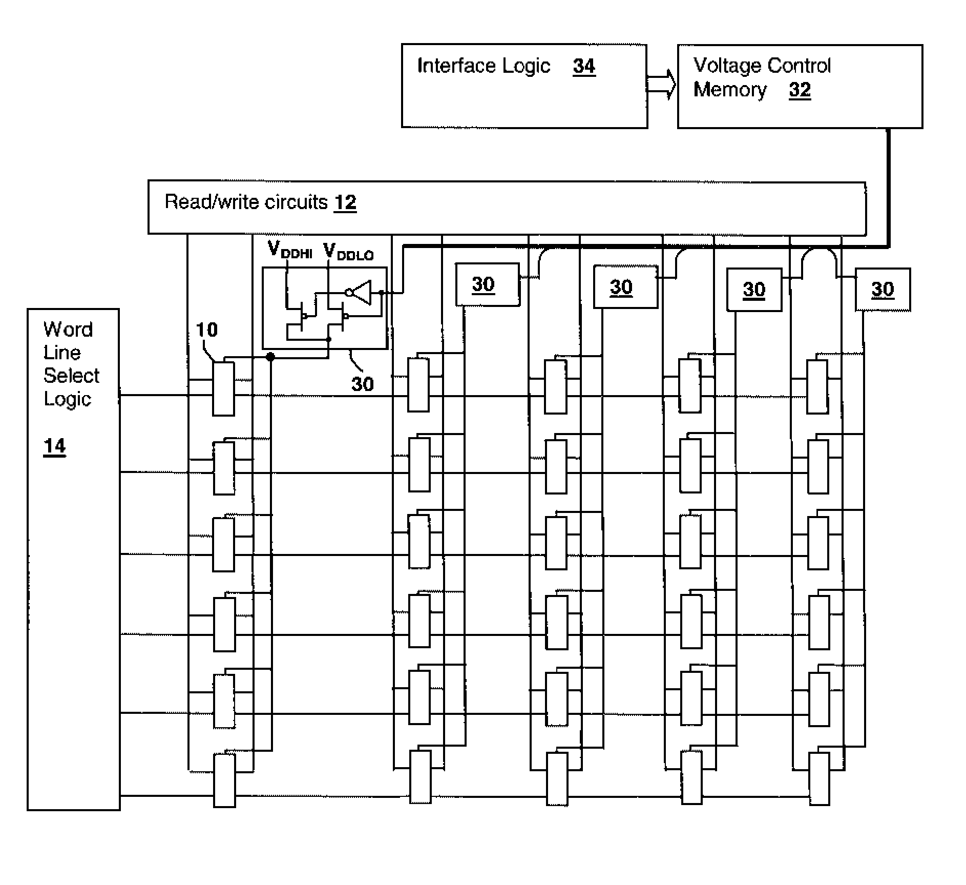
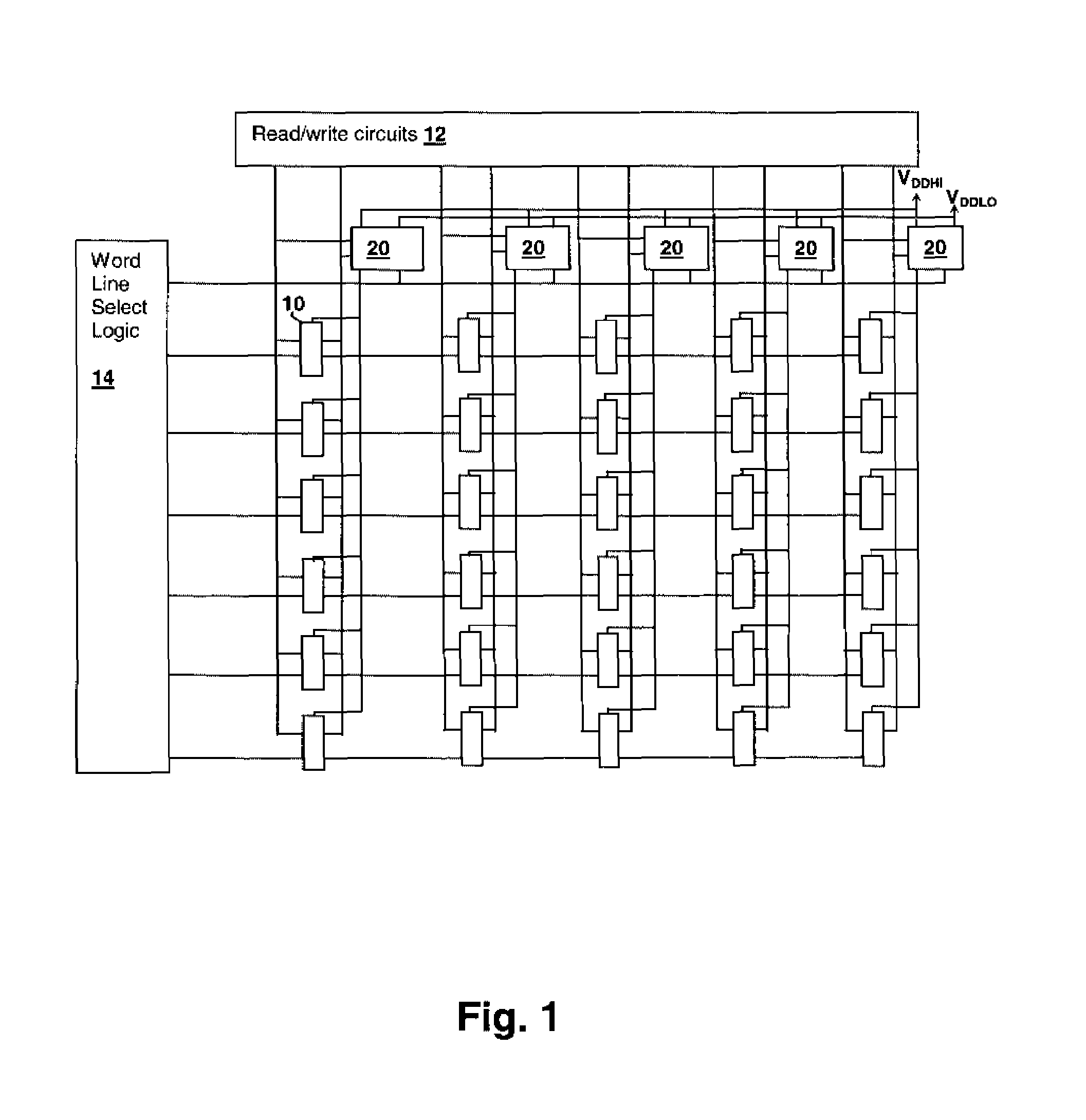
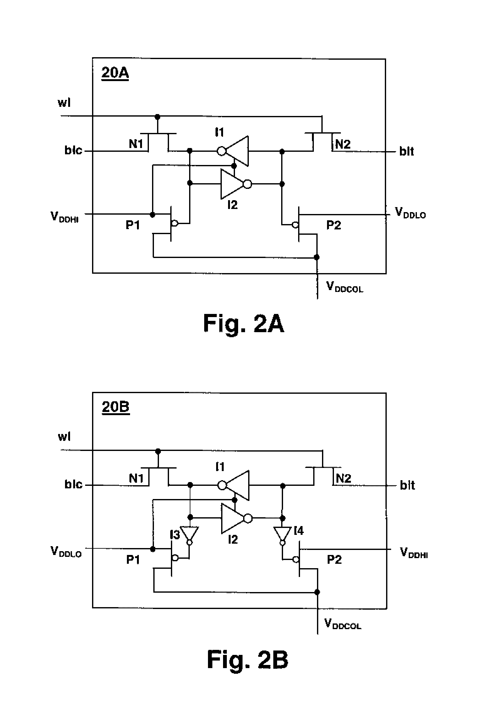
[0022]The present invention concerns storage devices such as static random access memories (SRAMs), in which for a particular design, the power supply voltage supplied to the storage elements that make up the storage device is selected from among two or more different non-zero power supply voltages. By providing a selectable power supply voltage for individual elements within the storage device, the yield of a storage device production run can be increased, by increasing the voltage supplied to marginal elements for which full performance is not obtained at the lower power supply voltage. The marginal elements are generally detected during manufacturing test of the storage device. The above-incorporated U.S. patent application “METHOD AND SYSTEM FOR DETERMINING ELEMENT VOLTAGE SELECTION CONTROL VALUES FOR A STORAGE ARRAY” discloses and claims methods and systems for obtaining initial voltage selection values for controlling the storage device of the present invention. However, selec...


PUM


Abstract

An energy efficient storage device using per-element selectable power supply voltages provides energy conservation in storage devices while maintaining a particular performance level. The storage device is partitioned into multiple elements, which may be sub-arrays, rows, columns or individual storage cells. Each element has a corresponding virtual power supply rail that is provided with a selectable power supply voltage. The power supply voltage provided to the virtual power supply rail for an element is set to the minimum power supply voltage unless a higher power supply voltage is required for the element to meet performance requirements. A control cell may be provided within each element that provides a control signal that selects the power supply voltage supplied to the corresponding virtual power supply rail. The state of the cell may be set via a fuse or mask, or values may be loaded into the control cells at initialization of the storage device.

Description

CROSS-REFERENCE TO RELATED APPLICATION[0001]This application is related to co-pending U.S. patent application Ser. No. 11 / 941,161, filed concurrently herewith and entitled “METHOD AND SYSTEM FOR DETERMINING ELEMENT VOLTAGE SELECTION CONTROL VALUES FOR A STORAGE DEVICE”, by the same inventors and assigned to the same Assignee. The above-referenced U.S. patent application is incorporated herein by reference.BACKGROUND OF THE INVENTION[0002]1. Technical Field[0003]The present invention relates generally to storage devices, and more particularly to a storage device having per-element selectable power supply voltages.[0004]2. Description of the Related Art[0005]Storage array energy usage vs. performance is a critical trade-off in present-day processing systems. System memory, as well as internal and external processor caches and internal registers, consume a large portion of total system power, particularly in network server systems in which processors and memory modules form the majorit...

Claims


Application Information

Patent Timeline
Patent Type & Authority Patents(United States)
IPC IPC(8): G11C5/14
CPCG11C5/14G11C11/417
Inventor JOSHI, RAJIV V.KUANG, JENTE BKANJ, ROUWAIDA N.NASSIF, SANI R.NGO, HUNG CAI
Owner GLOBALFOUNDRIES INC
Learn More