Superconductor current limiting system and method
a current limiter and superconductor technology, applied in the direction of superconductor elements, superconductor protection arrangements, emergency protective arrangements for limiting excess voltage/current, etc., can solve the problems of all three lines and the neutral conductor, faults in the system, and resistors costing au$250,000 to purchase and install
Inactive Publication Date: 2009-06-23
S C POWER SYST
View PDF6 Cites 11 Cited by
- Summary
- Abstract
- Description
- Claims
- Application Information
AI Technical Summary
Benefits of technology
"The present invention provides a fault current limiter for reducing neutral earth fault currents in an electrical network. The fault current limiter includes a series of phase coils and a series of neutral coils located adjacent a superconductive coil for fault current limiting phase and neutral earthing faults, respectively. The neutral coils are preferably formed around a high permeability core and the superconductive coil can encompass a central core formed from a high permeability material. The phase coils and the neutral coils are magnetically coupled to the central core. The method of current limiting earthing faults in an electrical network involves using a fault current limiter between the network and ground, while the method of current limiting faults in a multi-phase electrical network involves using a superconductive phase fault current limiter between each phase of the network and a transformer, and a superconductive neutral fault current limiter between the neutral of the transformer and the network. The superconductive phase fault current limiters and the superconductive neutral fault current limiter share the same cryostat and the same superconductive coil. The technical effect of the invention is to reduce the risk of damage to electrical equipment due to current faults in the network."
Problems solved by technology
Further, authorities often mandate that faults in the system should be dealt with in a controlled manner.
In addition, this fault may occur between all three lines and the neutral conductor, such as when a cable, with a neutral connected as an earthed shield, is severed by excavation equipment.
These resistors can cost in the vicinity of AU$250,000 to purchase and install and are a significant undertaking.
The use of neutral earthing resistors has a number of problems.
Firstly, they are only useful when the fault is to ground.
Secondly, they increase the voltage stress on the other phases when a fault occurs.
They often require extra insulation of the neutral, require extra expense for transformers and are not cost effective unless protection is also upgraded.
This option often requires a substantial investment in capital and labour and is only effective as long as the fault level remains below the fault level of the new switchgear.
This is not always true because subsequent additional transformers, and / or a reduction in the substation source impedance, can lead to the future fault level increasing beyond the new switchgear rating.
However, this gain is at the expense of reduced reliability.
Operating on a split bus means that if one transformer fails, all the load (i.e customers) connected on that transformer will lose supply until they can be switched over to the remaining good transformer.
Hence, it is not desirable for a utility or electrical network owner to operate in the split bus mode.
This technique, however, often leads to voltage regulation problems as the impedance also exists during normal operating conditions.
However, this again is likely to led to substantial extra expense, and is an unlikely solution for existing substations.
In addition, this technique is not future proof as the addition of a further transformer at some future time will increase fault levels again.
Method used
View moreImage
Smart ImageViewing Examples

Examples
case 1
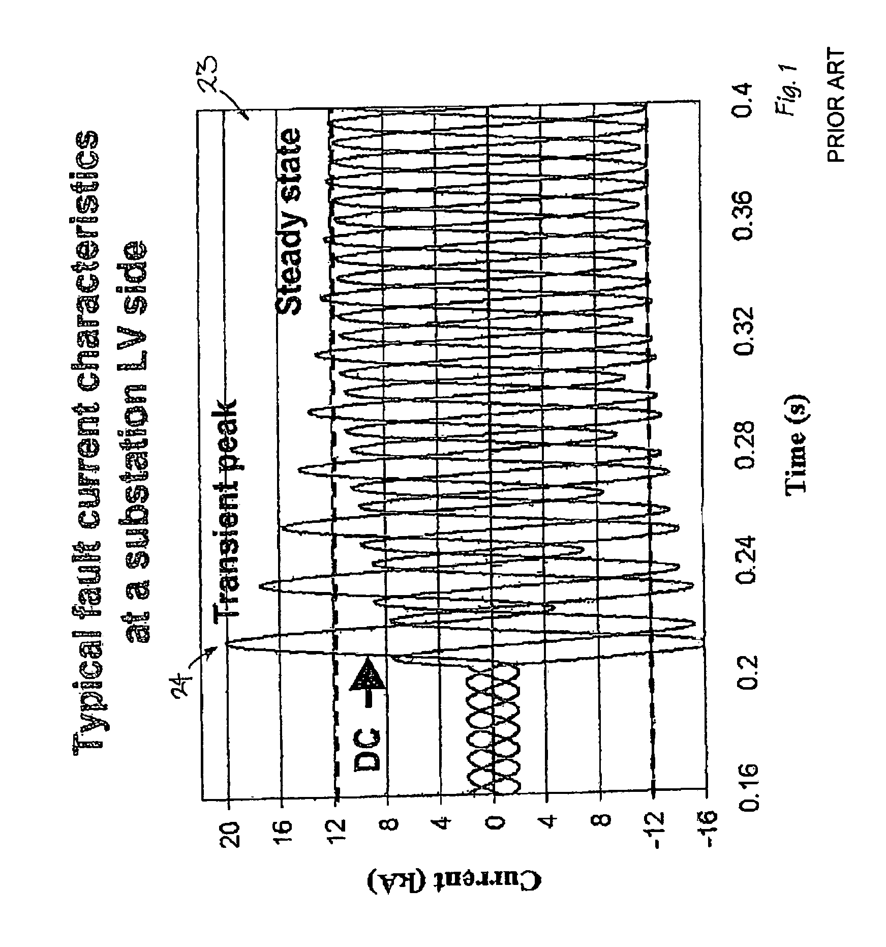
[0085]Base case—no fault limiting devices at the substation
case 2
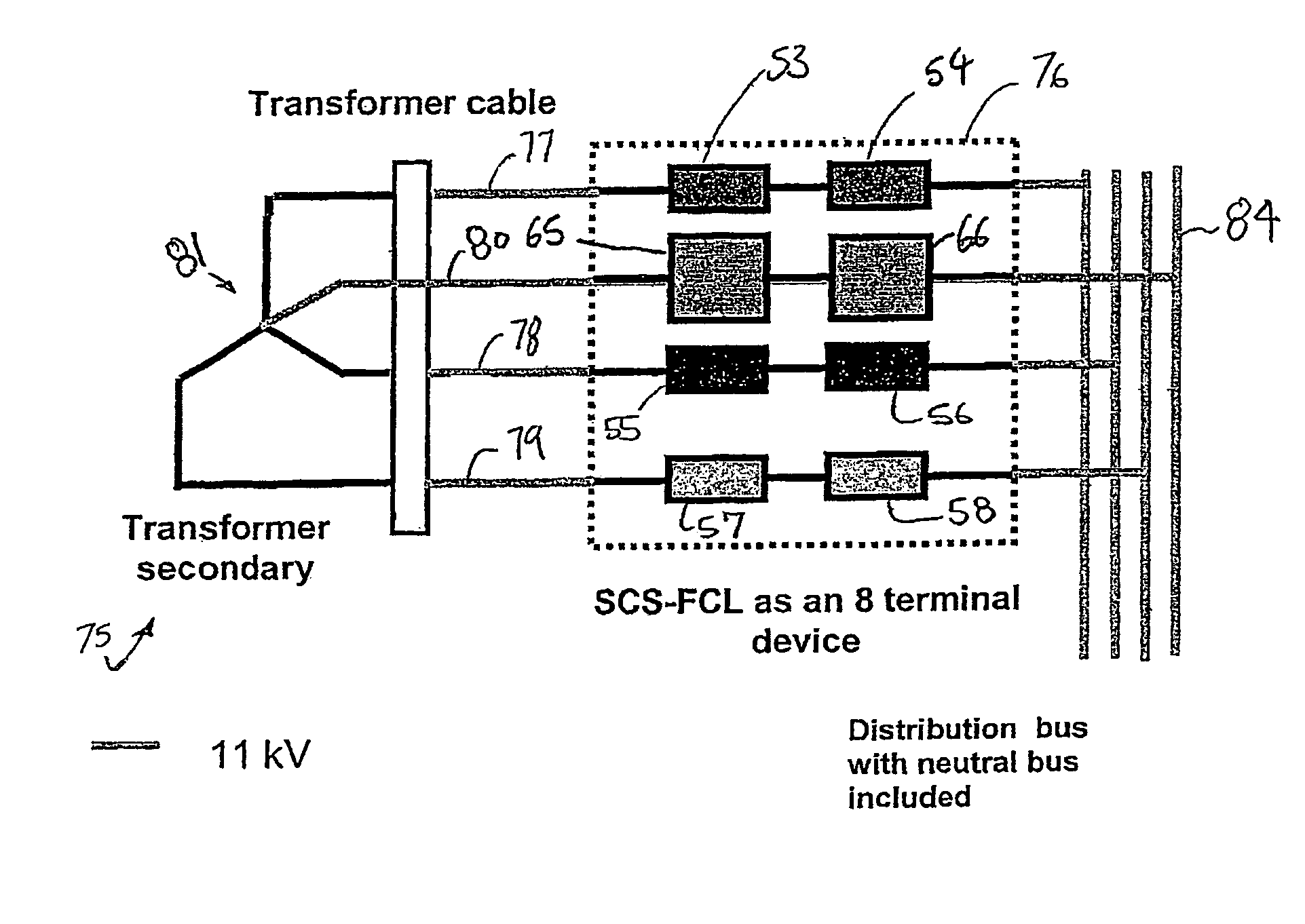
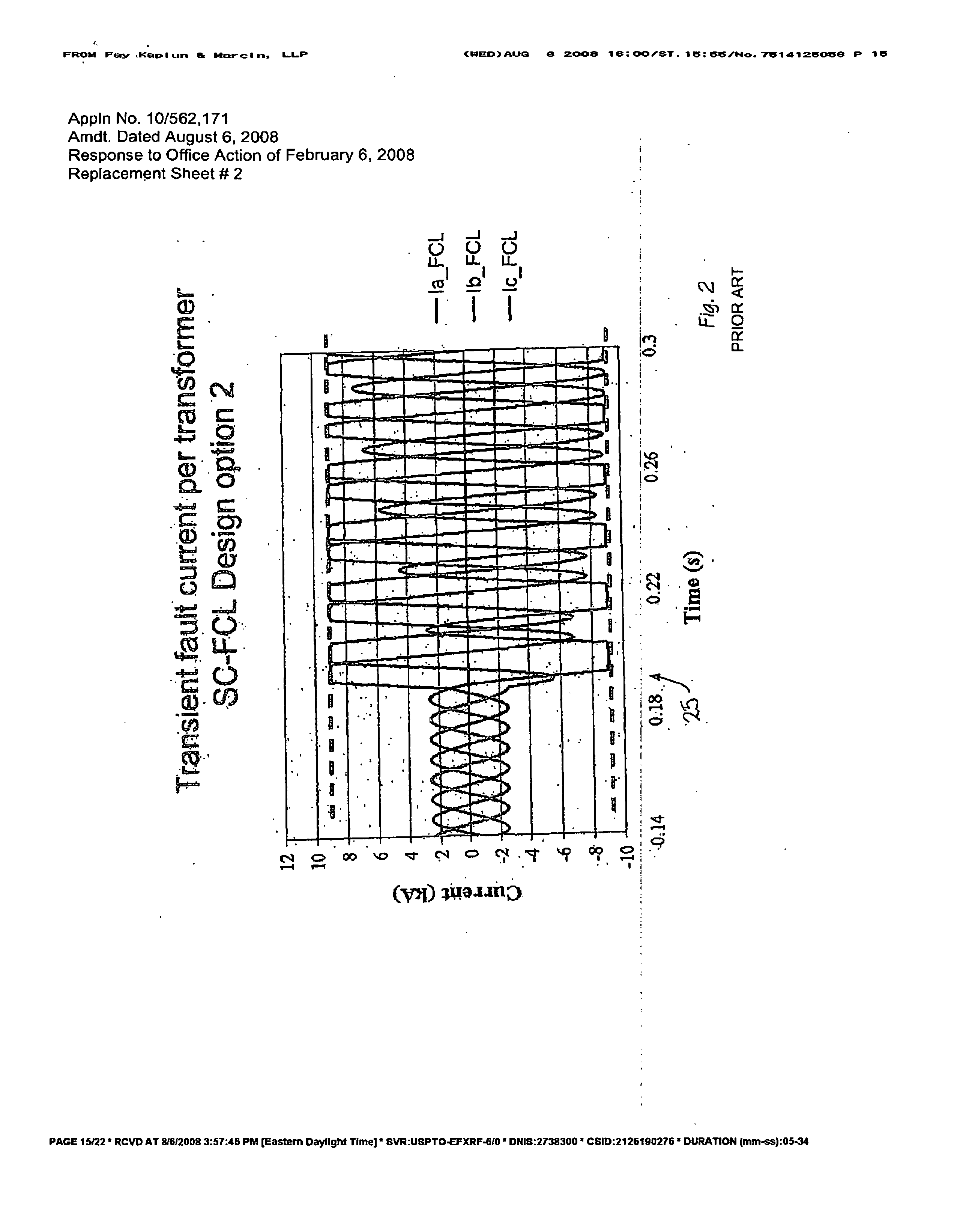
[0086] A HTS-FCL of a six terminal design limiting three phase currents
case 3
[0087] An NER only, severely limiting earth fault current to about 1 kA
Login to View More PUM
 Abstract
A fault current limiter for limiting current faults in an electrical network comprising: a series of phase coils located adjacent a superconductive coil for fault current limiting phase faults within the network; a series of neutral coils located adjacent the superconductive coil for fault current limiting neutral earthing faults in the electrical network.
Description
PRIORITY CLAIM[0001]This application claims the benefit of PCT Application Serial No. PCT / AU04 / 00906, filed on Dec. 21, 2005, which claims the benefit of Australian Patent Application No. 2003903489, filed on Jul. 7, 2003, the specifications of which are expressly incorporated herein, in their entirety, by reference.FIELD OF THE INVENTION[0002]The present invention relates to the field of superconductor fault current limiters and, in particular, discloses a high temperature superconductor (HTS) fault current Limiter (FCL) having a design utilising either split and solid limb cores or a combination of both in addition to providing for neutral earthing coils for limiting earth fault currents.BACKGROUND OF THE INVENTION[0003]The discovery of high temperature superconductors has lead to the development of a number of applications for their use. Superconductors are known to have the property that they have zero direct current (DC) resistance below a critical temperature Tc. They also hav...
Claims
Login to View More Application Information
Patent Timeline
 Patent Type & Authority Patents(United States)
IPC IPC(8): H02H7/00H02H9/02H02H9/08H10N60/30
CPCH02H9/023H02H9/08Y02E40/69Y10S505/85Y02E40/60
Inventor DARMANN, FRANCIS ANTHONY
Owner S C POWER SYST
Features
- R&D
- Intellectual Property
- Life Sciences
- Materials
- Tech Scout
- Unparalleled Data Quality
- Higher Quality Content
- 60% Fewer Hallucinations
Learn More Browse by: Latest US Patents, China's latest patents, Technical Efficacy Thesaurus, Application Domain, Technology Topic, Popular Technical Reports.
© 2025 PatSnap. All rights reserved.Legal|Privacy policy|Modern Slavery Act Transparency Statement|Sitemap|About US| Contact US: help@patsnap.com