
PHEMT structure having recessed ohmic contact and method for fabricating same

Active Publication Date: 2009-06-23
SKYWORKS SOLUTIONS INC
View PDF6 Cites 3 Cited by
  • Summary
  • Abstract
  • Description
  • Claims
  • Application Information

AI Technical Summary

Benefits of technology

[0007]The present invention is directed to a PHEMT structure having a recess ohmic contact and method for fabricating same. The present invention addresses and resolves the need in the art for a PHEMT structure which provides reduced on-state resistance without compromising performance or reliability.

Problems solved by technology

However, since gate length reduction is currently at the limits of process capabilities, new photolithography processes and equipment will be required to further reduce gate length.
However, catastrophic gate to drain leakage can occur if source to drain spacing is reduced too much.
However, although providing a minimal reduction in on-state resistance, increasing Schottky layer thickness can have the undesirably effect of significantly decreasing pinch-off voltage.

Method used


Image

  • PHEMT structure having recessed ohmic contact and method for fabricating same
  • PHEMT structure having recessed ohmic contact and method for fabricating same
  • PHEMT structure having recessed ohmic contact and method for fabricating same

Examples


Embodiment Construction

[0015]The present invention is directed to a PHEMT structure having a recessed ohmic contact and method for fabricating same. The following description contains specific information pertaining to the implementation of the present invention. One skilled in the art will recognize that the present invention may be implemented in a manner different from that specifically discussed in the present application. Moreover, some of the specific details of the invention are not discussed in order not to obscure the invention. The specific details not described in the present application are within the knowledge of a person of ordinary skill in the art.

[0016]The drawings in the present application and their accompanying detailed description are directed to merely exemplary embodiments of the invention. To maintain brevity, other embodiments of the invention which uses the principles of the present invention are not specifically described in the present application and are not specifically illus...


PUM


Abstract

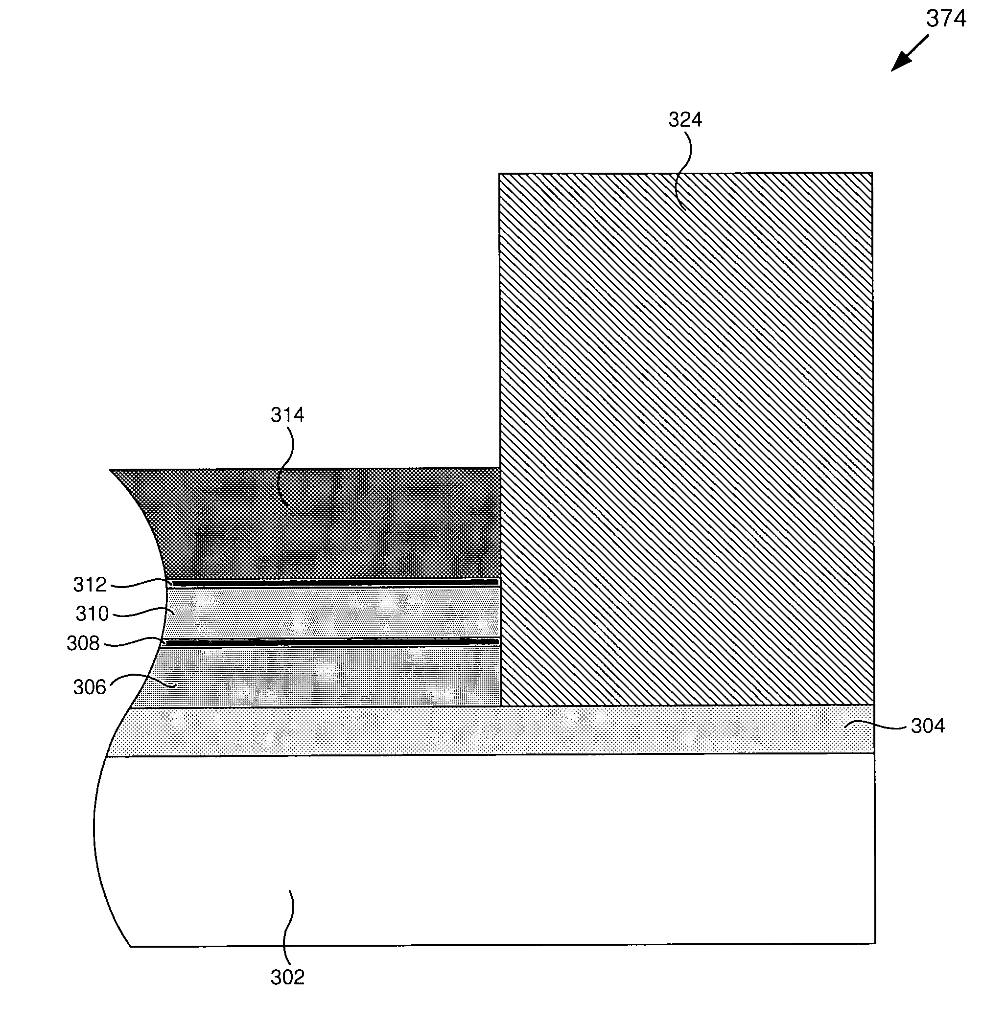
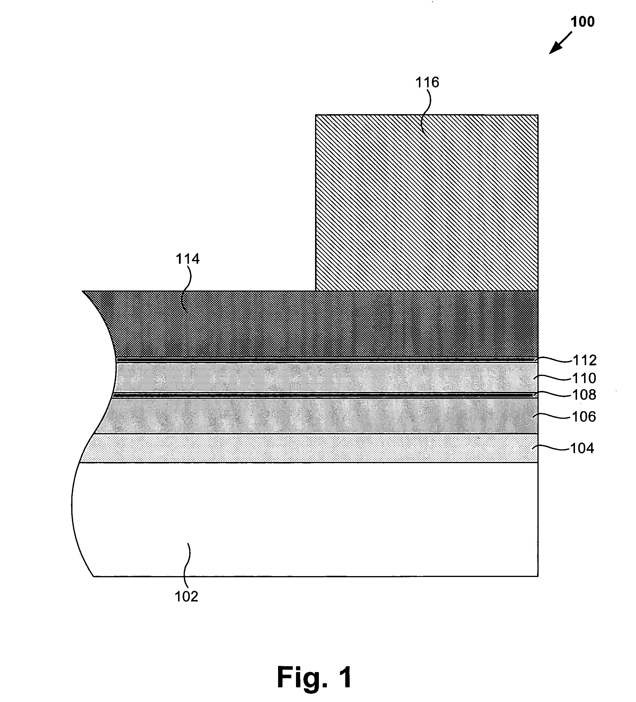
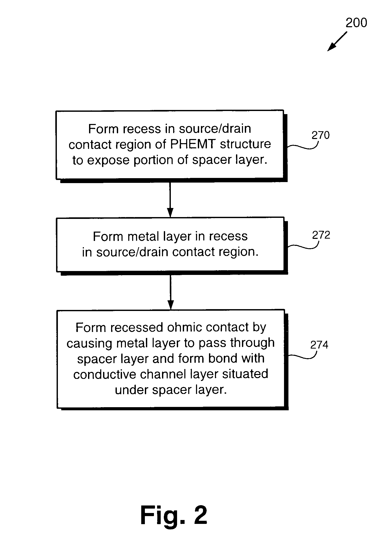
According to an exemplary embodiment, a PHEMT (pseudomorphic high electron mobility transistor) structure includes a conductive channel layer. The PHEMT structure further includes at least one doped layer situated over the conductive channel layer. The at least one doped layer can include a heavily doped layer situated over a lightly doped layer. The PHEMT structure further includes a recessed ohmic contact situated on the conductive channel layer, where the recessed ohmic contact is situated in a source / drain region of the PHEMT structure, and where the recessed ohmic contact extends below the at least one doped layer. According to this exemplary embodiment, the recessed ohmic contact is bonded to the conductive channel layer. The recessed ohmic contact is situated adjacent to the at least one doped layer. The PHEMT structure further includes a spacer layer situated between the at least one doped layer and the conductive channel layer.

Description

BACKGROUND OF THE INVENTION[0001]1. Field of the Invention[0002]The present invention is generally in the field of semiconductors. More specifically, the invention is in the field of pseudomorphic high electron mobility transistor structures.[0003]2. Background Art[0004]In many applications, it is desirable to reduce the “on-state” resistance of transistors, such as field effect transistors (FETs) and, more particularly, pseudomorphic high electron mobility transistors (PHEMTs), without compromising performance or reliability. By way of background, the on-state resistance of a PHEMT refers to the source to drain resistance as measured while the PHEMT is in an operating state.[0005]Various methods have been attempted in the art in an effort to reduce the on-state resistance of PHEMT structures. One method attempts to reduce gate length to achieve reduced on-state resistance. However, since gate length reduction is currently at the limits of process capabilities, new photolithography ...

Claims


Application Information

Patent Timeline
IPC IPC(8): H01L29/08
CPCH01L29/205H01L29/41766H01L29/66462H01L29/7787H01L29/452
Inventor MASON, JEROD F.BARTLE, DYLAN C.
Owner SKYWORKS SOLUTIONS INC
Learn More