
Device and method for estimating the noise of a video signal

a video signal and noise estimation technology, applied in the field of video signal noise estimation devices and methods, can solve the problems of poor image reconstruction, overestimation of noise level, and inability to always be reliable, and achieve the effect of reducing negative effects, robust noise estimation, and good noise estimation

Active Publication Date: 2009-06-16
BURLEY LICENSING LLC
View PDF8 Cites 5 Cited by
  • Summary
  • Abstract
  • Description
  • Claims
  • Application Information

AI Technical Summary

Benefits of technology

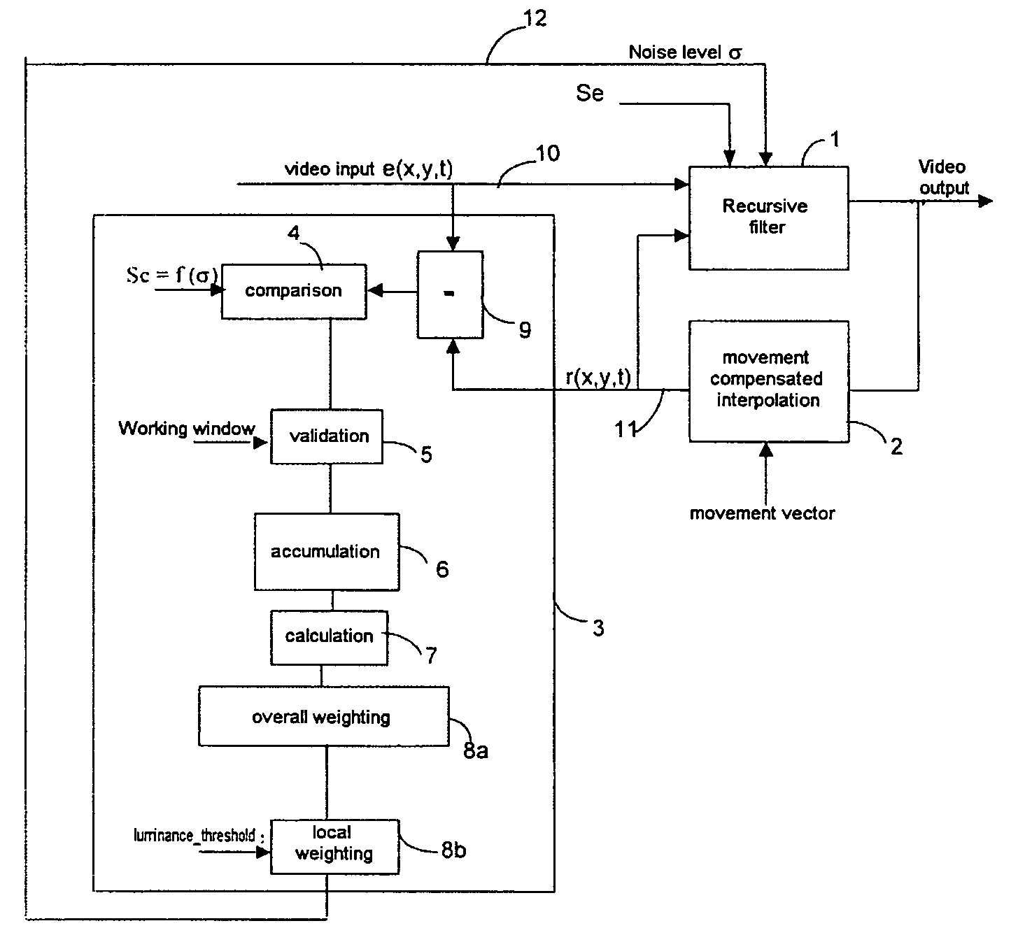
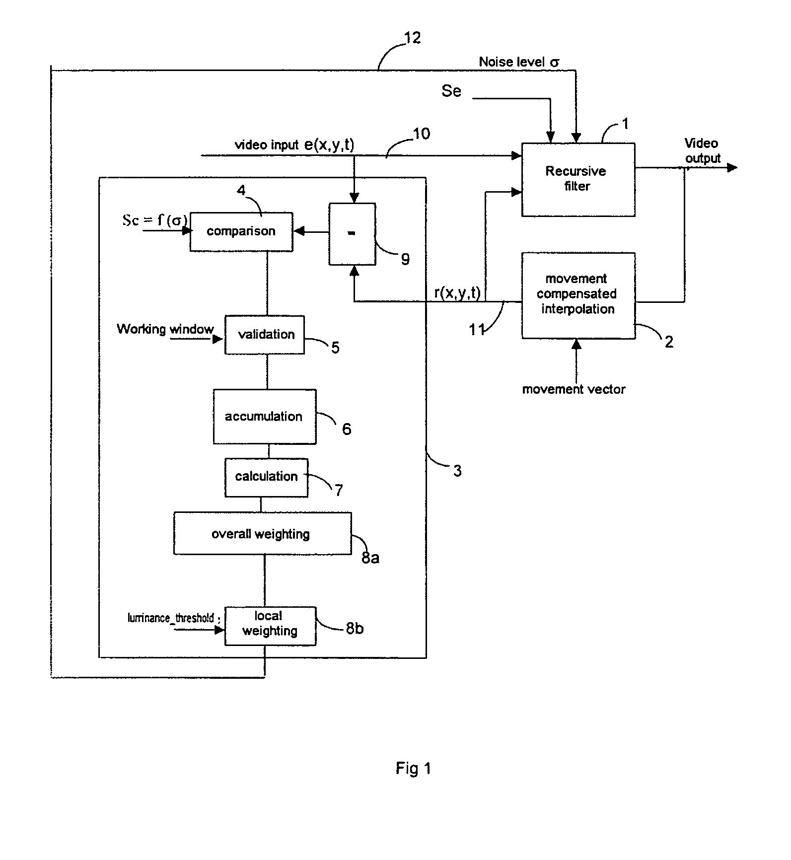
[0011]The present invention relates to a robust noise estimating device using the pixel-by-pixel difference between the source image and the filtered image, delayed by one image and movement compensated in order to obtain a good estimation of the noise, by considerably reducing the negative effects explained above.
[0017]This device can make the estimation of the noise level in a video sequence robust and improve the performance of a noise reducer to which it would be linked.
[0019]This can allow for a better estimation of noise level for each pixel and so avoid an overall estimation which would generate blurring effects on the frame.
[0024]Such a working window allows for a better estimation of the noise level by achieving independence from potential movement vector computation errors around the edges of the image.

Problems solved by technology

However, such methods present numerous drawbacks:the movement vector can produce estimation errors, provoking a poor reconstruction of the image and therefore an overestimation of the noise level, since there is movement in the image sequence,the movement vector and therefore the differences between images (Displaced Frame Difference DFD), are inconsistent all around the perimeter of the image, which also falsifies the estimation of the noise level,the estimation of the noise level is based on the random nature of the noise, which is not always reliable.

Method used


Image

  • Device and method for estimating the noise of a video signal
  • Device and method for estimating the noise of a video signal
  • Device and method for estimating the noise of a video signal

Examples


first embodiment

[0101]In a first embodiment, the threshold Se can be linked linearly to a filtering severity degree.

[0102]For example, if it is assumed that there is a five-position filtering adjustment cursor (cursor-position), the following value can be assigned to Se:

[0103]Se=16+cursor_position, 16 being a value set arbitrarily.

second embodiment

[0104]In a second embodiment, Se can be adapted to the noise level σ and so vary it for each frame.

third embodiment

[0105] the threshold can be modified dynamically and locally and adapted to characteristic areas of the image being processed. Thus, for the movement areas, the risk of artefacts increases and it is preferable to lower the value of the threshold Se. For the low movement areas, the threshold value can be higher.

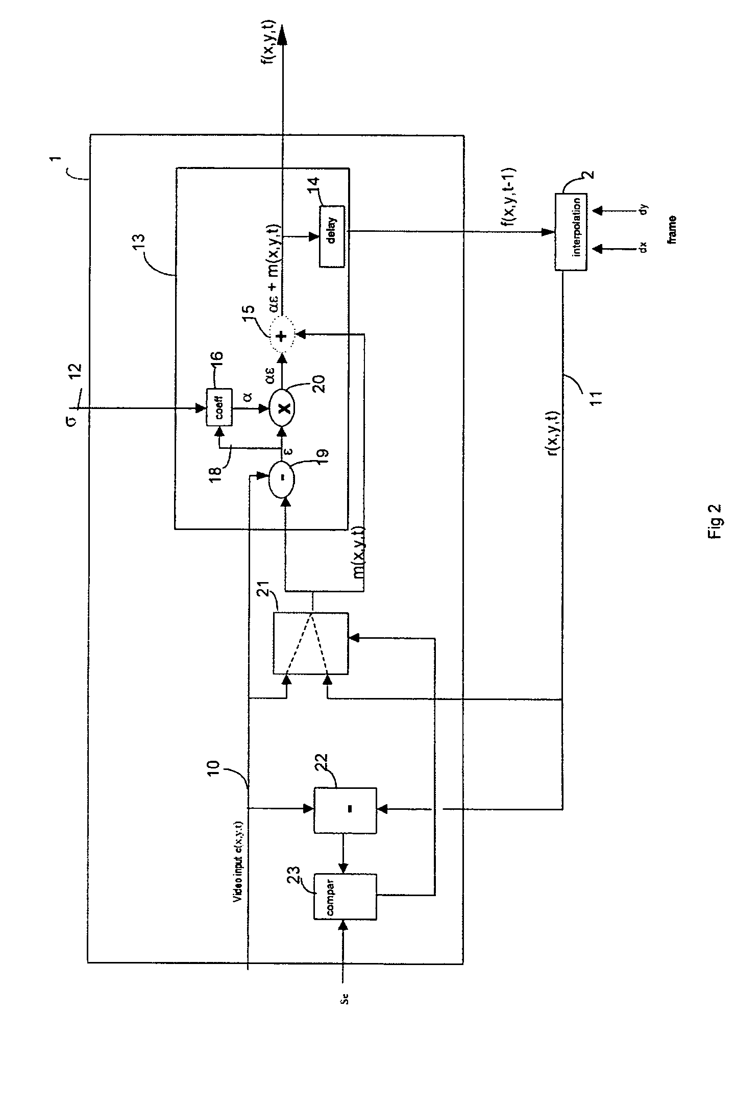
[0106]The multiplexer 21 directs towards an input of the recursive filter the video signal e(x,y,t) or the movement compensated output r(x,y,t) depending on the threshold Se.

[0107]The multiplexer can be used to sort between the real noise and the compensation errors.

[0108]The comparator 23 generates a control signal to the multiplexer 21.

[0109]If g(x,y,t)>Se, then the control signal sent to the multiplexer 21 tells the multiplexer 21 to send the video signal e(x,y,t) to the recursive filter 13.

[0110]If g(x,y,t)21 tells the multiplexer 21 to send the movement compensated output r(x,y,t) to the recursive filter 13.


PUM


Abstract

The disclosure relates to a device and a method for estimating the noise level of a video signal representing image sequences. The device comprises a movement compensated interpolation means, a recursive filter designed to receive on a first input the output of the recursive filter movement compensated by the movement compensated interpolation means and on a second input the video signal, means of calculating the difference between the video signal and the output of the recursive filter movement compensated by the movement compensated interpolation means. In accordance with the principles of the invention, the device comprises means of estimating the noise level of the video signal according to the difference and a maximum threshold delimiting this difference.

Description

[0001]This application claims the benefit, under 35 U.S.C. 119, of French patent application No. 0312007 filed Oct. 14, 2003.[0002]The present invention relates to a device and a method for estimating the noise level of a video signal, and a noise reduction system and an encoding system including such a device.BACKGROUND OF THE INVENTION[0003]Noise reduction is an important factor in pre-encoding video preprocessing. It is based on recursive time domain filtering, for which the recursion rate is adjusted according to the noise level present in the sequence of images to be processed.[0004]Estimation of the noise level is therefore important for obtaining a filtering system which adapts automatically to the sequence of incoming images.[0005]In known methods, in the total absence of movement and because of its time-random nature, the noise can be detected by establishing the pixel-by-pixel difference between two consecutive images. The average of the differences in an image then consti...

Claims


Application Information

Patent Timeline
Patent Type & Authority Patents(United States)
IPC IPC(8): H04N5/217H04N5/21H04N7/24H04N17/00H04N17/04
CPCH04N5/21H04N17/00H04N17/04
Inventor BABONNEAU, JEAN-YVESDIEUMEGARD, JACKYLE MEUR, OLIVIER
Owner BURLEY LICENSING LLC
Learn More