
Attachment structure of EA component

a technology of ea components and attachment structures, which is applied in the directions of roofs, pedestrian/occupant safety arrangements, vehicular safety arrangements, etc., can solve the problem of time-consuming process, and achieve the effect of significantly improving the workability of attaching the ea component to a member such as a trim

Inactive Publication Date: 2009-06-16
BRIDGESTONE CORP
View PDF28 Cites 42 Cited by
  • Summary
  • Abstract
  • Description
  • Claims
  • Application Information

AI Technical Summary

Benefits of technology

The present invention provides an attachment structure for an EA component that improves workability and attachment to a member. The attachment structure includes an EA component with a first locking part integrated with it, which is engaged with a second locking part in the member. The first locking part can be resiliently deformed and then resiliently restored to engage with the second locking part, allowing for easy attachment to the member. The first locking part can include a flange or a claw part that engages with the second locking part, and a base can be embedded in the EA component to increase bonding strength. The attachment structure can be used in automobile interiors to attach pads for head protection or pillar pads.

Problems solved by technology

Therefore, this process is time consuming.

Method used


Image

  • Attachment structure of EA component
  • Attachment structure of EA component
  • Attachment structure of EA component

Examples


Embodiment Construction

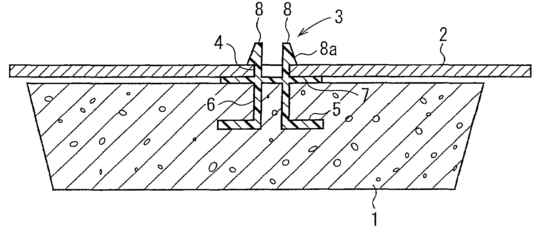
[0074]A preferred embodiment of a first aspect will now be described with reference to FIGS. 1a to 2b. FIG. 1a is a cross-sectional view in the substantially horizontal direction showing an attachment structure of an EA component according to this embodiment. FIG. 1b is a side view of a first locking part of the attachment structure of the EA component. FIG. 2a is a cross-sectional view showing a method for producing the EA component with the first locking part. FIG. 2b is an enlarged view of a part of FIG. 2a.

[0075]Referring to FIG. 1a, a sheet-shaped EA component 1 composed of a synthetic resin such as rigid urethane foam is attached to a trim 2 (a door trim in this embodiment) serving as a member, with a first locking part 3 therebetween. In this embodiment, an opening 4 serving as a second locking part is provided in the trim 2. The first locking part 3 is engaged with the opening 4. Although the opening 4 preferably has a round shape, the shape of the opening 4 is not limited ...


PUM


Abstract

In an attachment structure of an EA component, the EA component composed of a synthetic resin such as rigid urethane foam is attached to a trim serving as a member, with a first locking part therebetween. The first locking part includes a cylindrical part, an anchor, a flange, and a plurality of projections. The anchor has a flange shape extending from the rear end of the cylindrical part toward the outside. The flange extends from the leading end of the cylindrical part toward the outside. The projections protrude from the leading end of the cylindrical part in the direction parallel to the axis of the cylindrical part. The EA component is attached to the trim by setting the EA component on the trim while the projections are inserted in an opening.

Description

CROSS REFERENCE TO RELATED APPLICATION[0001]This application is a 371 of PCT / JP03 / 12765 filed on Oct. 6, 2003.BACKGROUND OF THE INVENTION[0002]1. Field of the Invention[0003]The present invention relates to an attachment structure of an impact energy-absorbing (EA) component, and in particular, to an attachment structure of an EA component that can be suitably applied to a trim or a roof component of automobiles.[0004]2. Description of the Related Art[0005]For the purpose of the impact energy absorption (EA) in case of side-on collision (i.e., side impact), an EA component composed of rigid urethane foam is attached to a door trim or a roof of automobiles. In a method for attaching an EA component composed of rigid urethane foam to a door trim, Japanese Unexamined Patent Application Publication No. 2001-322507 discloses the structure shown in FIGS. 3, 4a, and 4b. FIG. 3 is a cross-sectional view showing the attachment structure of an EA component disclosed in FIG. 7 in the above-cit...

Claims


Application Information

Patent Timeline
Patent Type & Authority Patents(United States)
IPC IPC(8): B60N99/00B60R13/02B60R13/08B60R21/04F16B5/06F16B21/07F16B21/08
CPCB60R13/0206B60R13/0815B60R21/04F16B5/0642F16B5/065F16B5/0657F16B5/0664F16B21/073F16B21/088F16F2226/00F16F2230/0047
Inventor HORIMATSU, TOSHIYUKISATO, MASATOSHI
Owner BRIDGESTONE CORP
Learn More