
Process for forming CMOS devices using removable spacers

a technology of cmos and spacers, which is applied in the manufacturing of semiconductor/solid-state devices, basic electric elements, electric devices, etc., can solve the problems of reducing the size of closely spaced cmos structures, void formation, and bridging defects in subsequently formed contacts, so as to reduce the occurrence of bridging defects and improve the gap-fill characteristics

Inactive Publication Date: 2009-06-09
INTEGRATED DEVICE TECH INC
View PDF6 Cites 9 Cited by
  • Summary
  • Abstract
  • Description
  • Claims
  • Application Information

AI Technical Summary

Benefits of technology

[0005]The resulting structure has sidewalls that are disposed at an angle greater than ninety degrees relative to the substrate. This sloped profile gives better gap-fill characteristics than prior art processes in which L-shaped spacers are used that have vertical sidewalls. Thereby, fewer voids are formed in the dielectric film, reducing the occurrence of bridging defects.
[0006]In the present embodiment, the first set of spacers have a slope that is approximately triangular, and a width that is less than the width of L-shaped spacers that are used in prior art CMOS processes that utilize disposable spacers. Accordingly, once the disposable spacers are removed, there is more available space between adjacent gate film stacks, allowing for locating gate film stacks closer together than is possible in conventional prior art processes in which wider L-shaped spacers are used.

Problems solved by technology

However, in applications where the spacing between adjacent gate structures is less than 0.2 microns, the vertical or nearly-vertical slope of the L-shaped spacer causes voids to form during deposition of the pre-metal dielectric layer.
These voids in the pre-metal dielectric layer can lead to bridging defects in the subsequently formed contacts.
In addition, the width of conventional L-shaped spacers takes up valuable space on the semiconductor surface, limiting size reduction of closely-spaced CMOS structures.

Method used


Image

  • Process for forming CMOS devices using removable spacers
  • Process for forming CMOS devices using removable spacers
  • Process for forming CMOS devices using removable spacers

Examples


Embodiment Construction

[0019]Reference will now be made in detail to the preferred embodiments of the invention, examples of which are illustrated in the accompanying drawings. While the invention will be described in conjunction with the preferred embodiments, it will be understood that they are not intended to limit the invention to these embodiments. On the contrary, the invention is intended to cover alternatives, modifications and equivalents, which may be included within the spirit and scope of the invention as defined by the appended claims. Furthermore, in the following detailed description of the present invention, numerous specific details are set forth in order to provide a thorough understanding of the present invention. However, it will be obvious to one of ordinary skill in the art that the present invention may be practiced without these specific details. In other instances, well-known methods, procedures, components, and circuits have not been described in detail so as not to unnecessarily...


PUM


Abstract

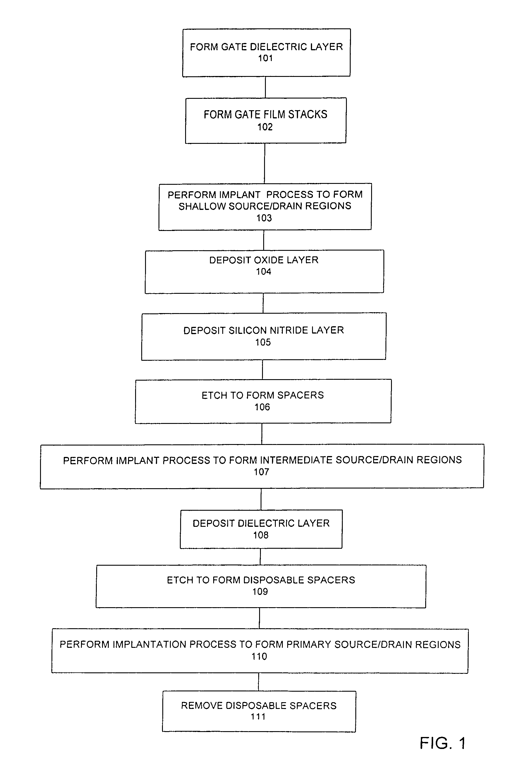
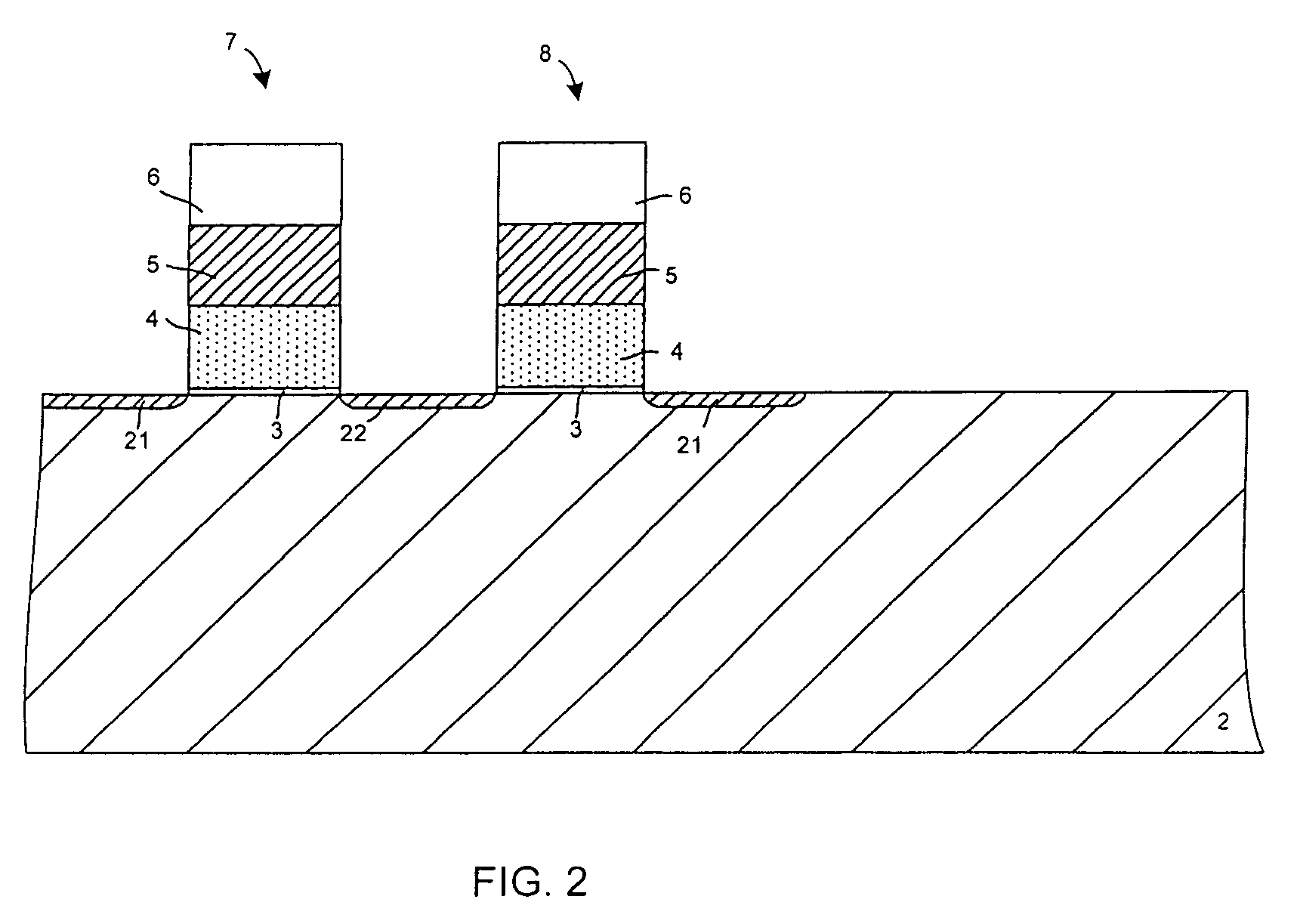
A process for forming CMOS devices is disclosed in which disposable spacers are used to obtain a structure having improved gap-fill characteristics. First, gate film stacks are formed on the substrate. A shallow implant process is performed so as to form shallow source / drain implant regions. A layer of oxide and a layer of silicon nitride are deposited and etched to form a first set of spacers that extend on opposite sides of the gate film stacks. A second implant is performed so as to form intermediate source / drain implant regions. A set of disposable spacers are then formed that extend on opposite sides of each of the gate film stacks. A third implant process is performed so as to form deep source / drain implant regions. The disposable spacers are then removed, providing more space for the subsequently-formed contact to land.

Description

FIELD OF THE INVENTION[0001]The present invention relates to the field of semiconductor devices. More particularly, the present invention relates to Complimentary Metal-Oxide Semiconductor (CMOS) manufacturing processes.BACKGROUND ART[0002]In sub-micron Complimentary Metal-Oxide Semiconductor (CMOS) manufacturing, disposable dielectric spacers are sometimes used to define the heavily doped contact region of a source / drain structure. In conventional processes that use disposable dielectric spacers, a first implant is performed prior to forming the first spacer. This first implant forms lightly-doped drain (LDD) regions. The L-shaped permanent spacer and the disposable spacer are then formed, with the disposable spacer overlying the L-shaped spacer. A second implant process is then performed so as to form the heavily doped contact region. The disposable spacer is then removed, leaving the L-shaped spacer. This process works well when there is sufficient space between adjacent gate str...

Claims


Application Information

Patent Timeline
Patent Type & Authority Patents(United States)
IPC IPC(8): H01L21/8238
CPCH01L21/28512H01L21/76897H01L21/823468H01L21/823475H01L21/823425
Inventor MUI, KENMARMORSTEIN, AARONLEE, ERIC
Owner INTEGRATED DEVICE TECH INC
Learn More