
Communication Module

a technology of communication module and communication module, applied in the field of communication module, can solve the problems of deterioration of light emitting element characteristic, especially high frequency characteristic, and generation of electric unbalance, and achieve the effect of improving the characteristic of light emitting element and high frequency characteristi

Inactive Publication Date: 2017-08-03
APRESIA SYST LTD
View PDF2 Cites 4 Cited by
  • Summary
  • Abstract
  • Description
  • Claims
  • Application Information

AI Technical Summary

Benefits of technology

The patent improves the quality of the optical element in a communication module, especially its high frequency performance.

Problems solved by technology

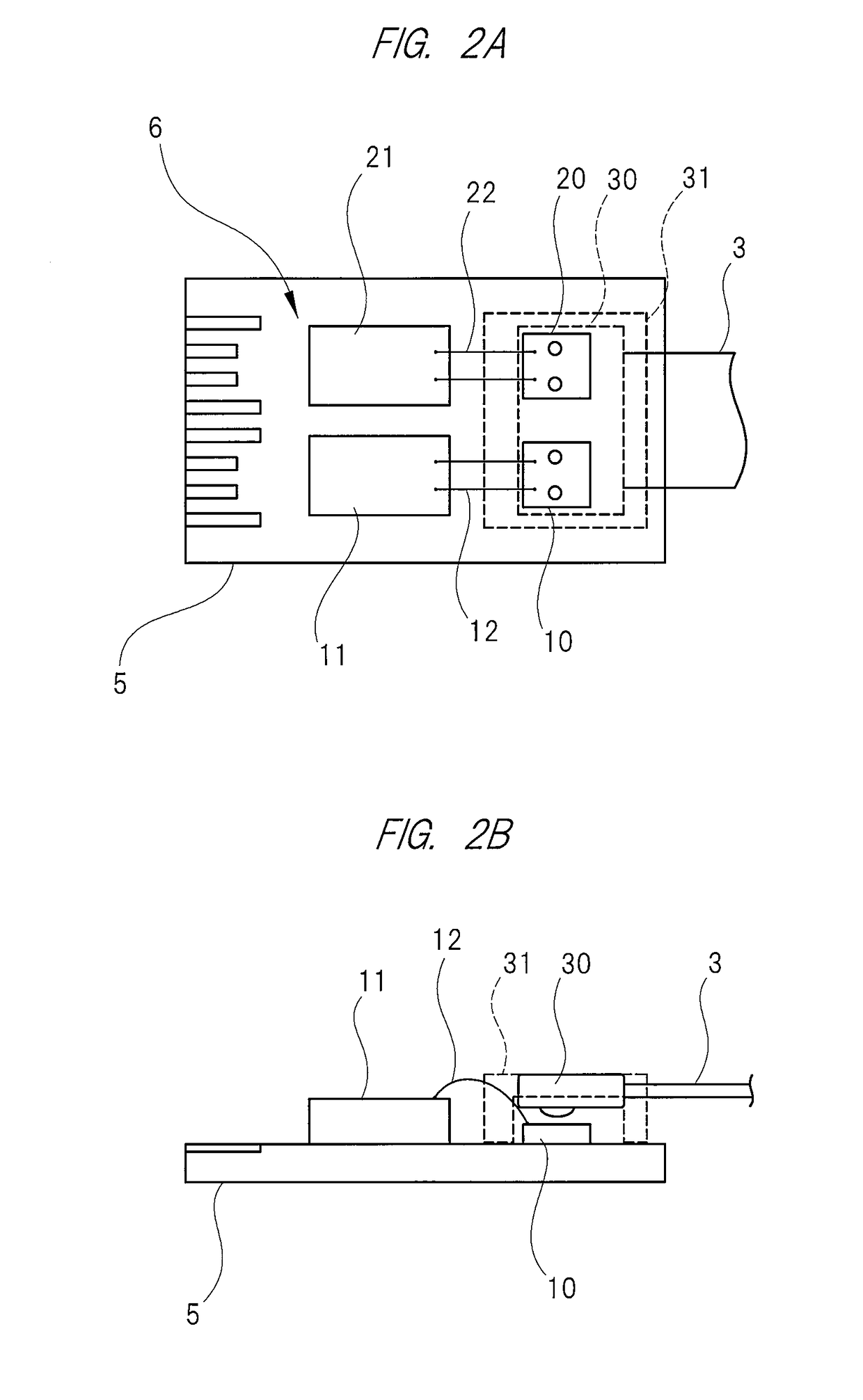
As a result, one + side electric current path and two − side electric current paths are formed between the light emitting element and the driving IC, and therefore electrical unbalance is generated and a characteristic of the light emitting element, especially a high frequency characteristic, is deteriorated.

Method used


Image

  • Communication Module
  • Communication Module
  • Communication Module

Examples


Embodiment Construction

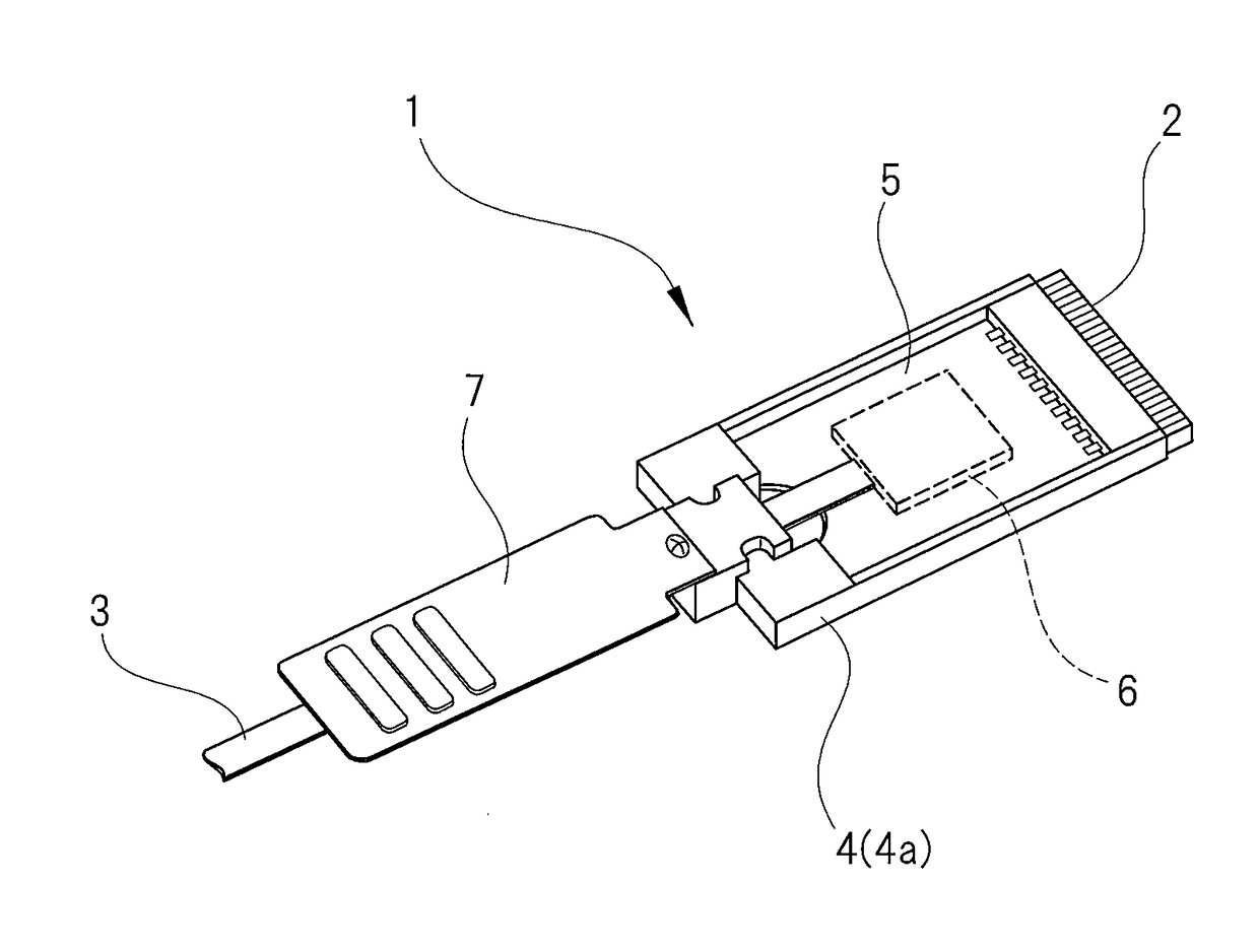
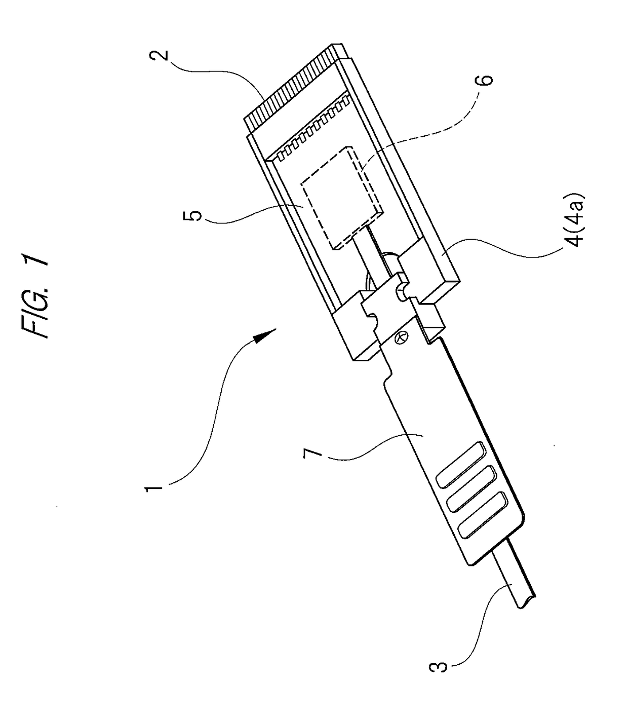
[0024]Hereinafter, one example of embodiments according to the present invention will be described. A communication module 1 shown in FIG. 1 is connected to a mother board installed in a communication device not shown so as to convert an optical signal into an electric signal and convert the electric signal into the optical signal. A plug connector 2 is provided at a tip end of the communication module 1, and the plug connector 2 is connected to a receptacle connector provided on the mother board. Namely, the communication module 1 according to the present embodiment has the plug connector 2 insertable to and removable from the receptacle connector provided on the mother board, and the communication module 1 and the mother board are connected via the plug connector 2 and the receptacle connector.

[0025]A communication semiconductor chip is mounted on the mother board to which the communication module 1 is connected as described above, and the communication module 1 connected to the m...


PUM


Abstract

A characteristic of an optical element, especially a high frequency characteristic, installed in a communication module is improved. The communication module has: a first and second front surface side metal layers provided on a front surface of a module substrate and electrically separated from each other; a first and second rear surface side metal layers provided on a rear surface of the module substrate and electrically separated from each other; a first thermal via bored through the module substrate and thermally connecting the first front and rear surface side metal layers; and a second thermal via bored through the module substrate and thermally connecting the second front and rear surface side metal layers. A driving IC is mounted on and thermally connected to the first front surface side metal layer. A light emitting element is mounted on and thermally connected to the second front surface side metal layer.

Description

CROSS-REFERENCE TO RELATED APPLICATION[0001]The present application claims priority from Japanese Patent Application No. 2016-019267 filed on Feb. 3, 2016, the content of which is hereby incorporated by reference into this application.TECHNICAL FIELD OF THE INVENTION[0002]The present invention relates to a communication module, and in particular relates to a communication module provided with a photoelectric conversion function.BACKGROUND OF THE INVENTION[0003]A general communication module comprises: a housing provided with a connector; and a substrate housed in the housing and electrically connected to the connector installed in the housing. The substrate installed in the communication module is generally called as “module substrate” which is distinguished from a substrate (generally called as “host board” or “mother board”) installed in a communication device such as a network switch or a server to which the communication module is connected. Hereinafter, in accordance with the d...

Claims


Application Information

Patent Timeline
IPC IPC(8): G02B6/42
CPCG02B6/4272G02B6/4246G02B6/4257G02B6/428
Inventor OGURA, AKIRAYAMAZAKI, KINYASATO, MASATAKAKOMATSUZAKI, SHINJI
Owner APRESIA SYST LTD
Learn More