PLL with low spurs

a low spur and cmos technology, applied in the direction of electrical equipment, pulse automatic control, etc., can solve the problem of poor performance and achieve the effect of low spurs and reliable operation

Active Publication Date: 2009-06-02
PICOSEMICON
View PDF4 Cites 4 Cited by
  • Summary
  • Abstract
  • Description
  • Claims
  • Application Information

AI Technical Summary

Benefits of technology

[0007]Embodiments of the present invention provide a PLL circuit which solves the low spurs operation problems of...

Problems solved by technology

There is a problem, however, when the application in which the overall IC is used requires the PLL circuit to have low spurs.
Prior art CMOS PLLs have tried to solve th...

Method used


Image

  • PLL with low spurs
  • PLL with low spurs
  • PLL with low spurs

Examples


Embodiment Construction

[0015]Reference will now be made in detail to the preferred embodiments of the present invention, examples of which are illustrated in the accompanying drawings. While the invention will be described in conjunction with the preferred embodiments, it will be understood that they are not intended to limit the invention to these embodiments. On the contrary, the invention is intended to cover alternatives, modifications and equivalents, which may be included within the spirit and scope of the invention as defined by the appended claims. Furthermore, in the following detailed description of embodiments of the present invention, numerous specific details are set forth in order to provide a thorough understanding of the present invention. However, it will be recognized by one of ordinary skill in the art that the present invention may be practiced without these specific details. In other instances, well-known methods, procedures, components, and circuits have not been described in detail ...


PUM


Abstract

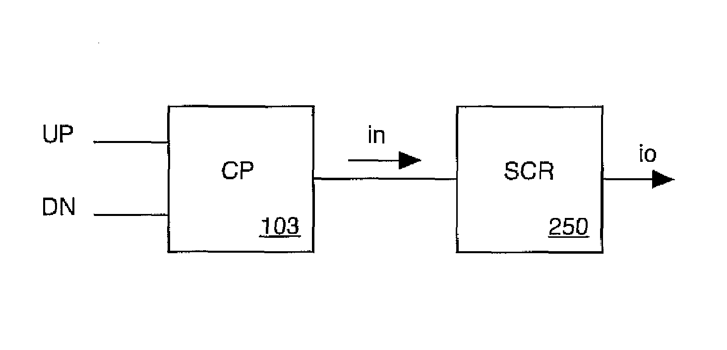
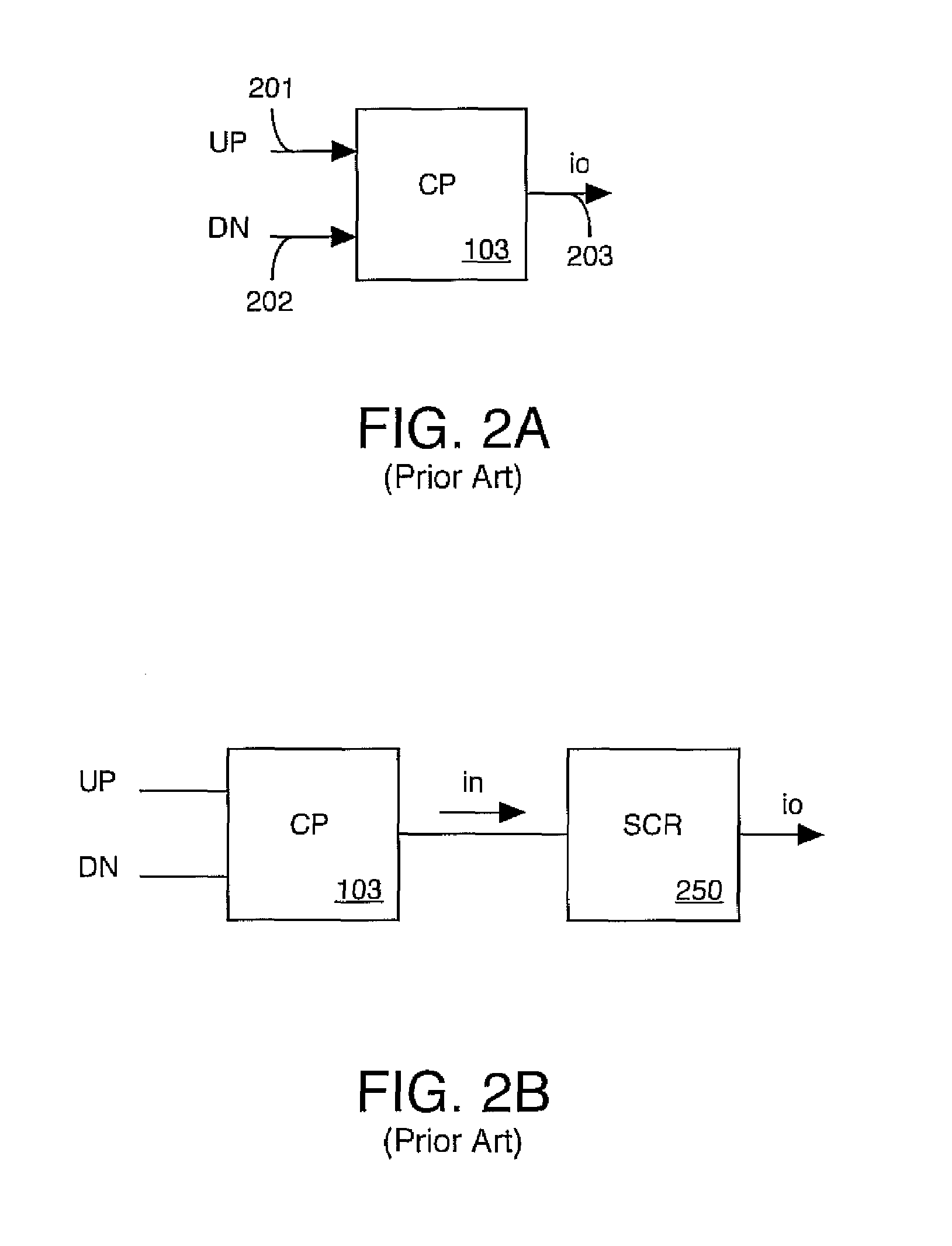
A PLL circuit having a low spur output. The PLL circuit includes a PFD (Phase-Frequency Detector), a charge-pump coupled to the PFD, an SCR (switch-capacitor resistor) coupled to the charge pump, a filter coupled to the SCR, and a VCO circuit coupled to the filter, wherein the SCR reduces an amplitude of a plurality of current pulses at an output of the charge-pump before the plurality of current pulses reach an input of the VCL circuit.

Description

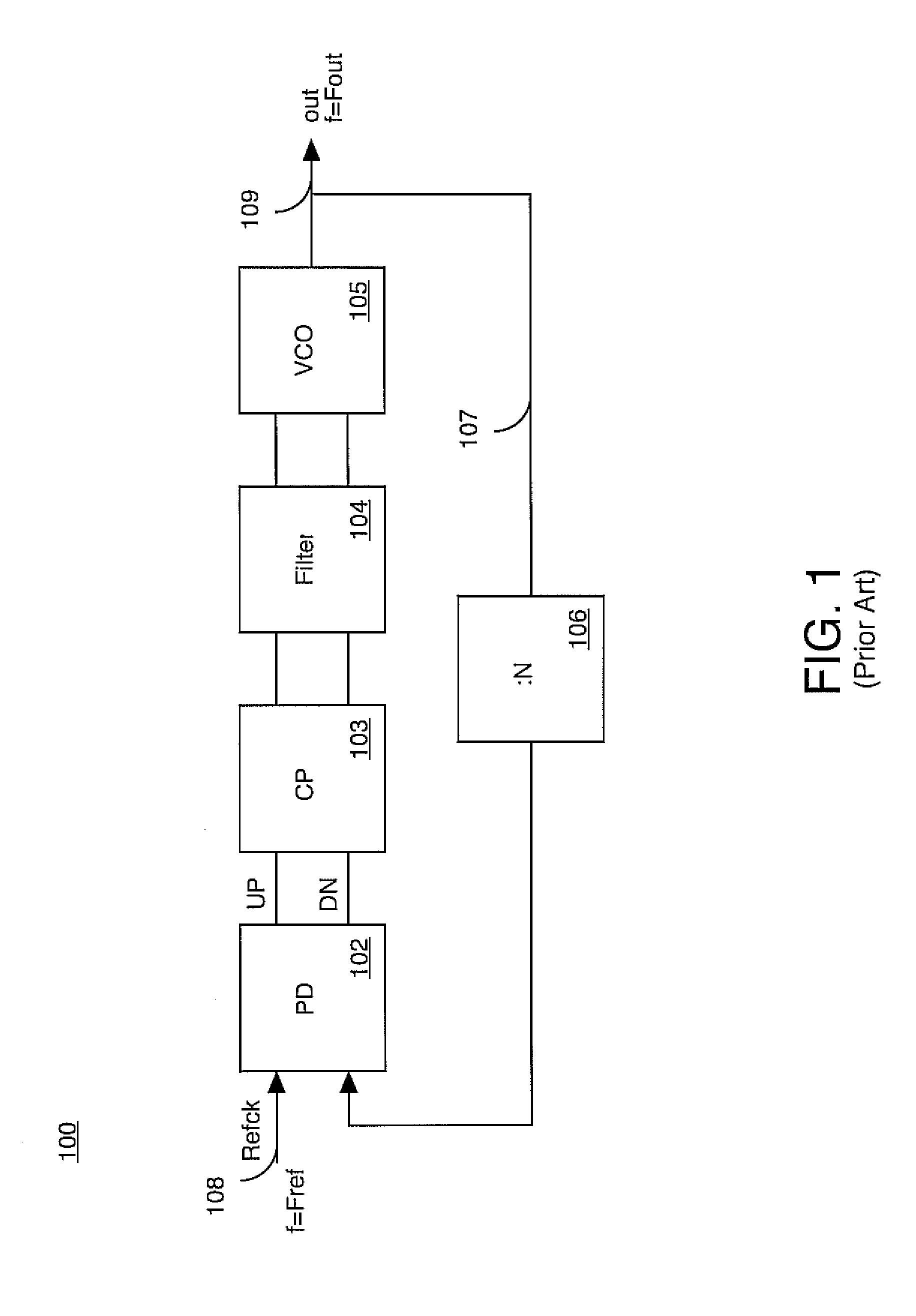
TECHNICAL FIELD[0001]The present invention relates to the field of CMOS technology Phase-Locked Loop (PLL). More particularly, the present invention relates to a low spurs CMOS PLL.BACKGROUND ART[0002]PLLs are well known and widely used in the electronics industry. Within the digital field, PLLs are used in a variety of applications. Such applications include, for example, frequency synthesizers, clock generation, clock recovery and the like. PLLs are typically designed to perform within a given set of boundary conditions and to perform according to a specified standard. Typical conditions include, for example, performance over operating temperature ranges, sensitivity to noise, output sensitivity to interference, and the like. Typical performance standards include, for example, output signal frequency stability, output signal programmability, and the like.[0003]A typical prior art PLL circuit generates an oscillating output signal having a specified frequency. The frequency of the ...

Claims


Application Information

Patent Timeline
IPC IPC(8): H03L7/06
CPCH03L7/0895H03L7/093
Inventor IRAVANI, KAMRAN
Owner PICOSEMICON
Why Eureka
Try Eureka