Eureka AIR delivers breakthrough ideas for toughest innovation challenges, trusted by R&D personnel around the world.

Explosive reactive armor with momentum transfer mechanism

a technology of momentum transfer mechanism and reactive armor, which is applied in the direction of reactive armor, protective equipment, transportation and packaging, etc., can solve the problems of inability to achieve the desired protection effect, and the failure to achieve the purpose of providing protection capability, so as to achieve the effect of improving interaction and maintaining protection capability

Active Publication Date: 2009-06-02
AGENCY FOR DEFENSE DEV
View PDF15 Cites 27 Cited by
  • Summary
  • Abstract
  • Description
  • Claims
  • Application Information

AI Technical Summary

Benefits of technology

[0008]Therefore, to solve the above problem, it is an object of the present invention to provide a new mechanism of an explosive reactive armor for thereby improving the interaction between a threat and an explosive reactive armor and maintaining a protection capability regardless of the impact angle including a right angle.
[0009]According to another object of the present invention, there is provided an explosive reactive armor capable of ensuring a superior protection capability even when a length of the threat is short, by promoting an interaction between the explosive reactive armor and a threat, and by inducing a multi-interaction between flying plates and a projectile so as to disturb the threat.
[0011]In order to realize the protection of an object by reducing a momentum of a threat when the threat from the outside penetrates the front plate member of the explosive reactive armor, when the reactive material continuously filled up within the closed loop detonates, the detonation wave moves along the closed loop faster than the threat, thereby changing an ongoing direction of the threat and simultaneously disrupting it into many pieces.
[0015]Flying elements, on the other hand, may additionally be mounted on an outer surface of the pairs of plates forming the front plate member, or on an inner surface of the pairs of plates forming the rear plate member. Accordingly, when the threat penetrates the front plate member and the detonation propagates along the closed loop, the flying elements move toward the inside of the closed loop as the detonation wave moves faster than the threat, which induces an interaction between the flying elements and the threat, thus to reduce a momentum of the threat and further to disrupt the threat.
[0016]The flying elements may be formed of at least one material among metals, ceramic materials, composite materials, or the like. In particular, when the ceramic materials are applied to the flying element, as the ceramic materials are light enough to increase a flight speed, thus, it can greatly reduce the kinetic energy of the threat when the threat impacts thereon.

Problems solved by technology

Thus, it is vulnerable for failing to achieve the purpose of providing a protection capability.
As a result, there has been a problem that it is impossible to achieve the desired protection effect.

Method used


Image

  • Explosive reactive armor with momentum transfer mechanism
  • Explosive reactive armor with momentum transfer mechanism
  • Explosive reactive armor with momentum transfer mechanism

Examples


first embodiment

[0031]FIG. 4 is a perspective view showing the construction of an explosive reactive armor with a momentum transfer mechanism in accordance with the present invention. The explosive reactive armor 100 with the momentum transfer mechanism according to the present invention includes: a front plate member 110 formed of a pair of flat spaced apart plates 111 and 112; a hemi-cylindrical rear plate member 120 formed of two concentric curved spaced apart plates 121 and 122 which are connected to the corresponding two flat plates 111 and 112 of the front plate member 110, respectively; and a reactive material 130 such as a high explosive charge filling in the gap between each of the two plates of the front plate member 110 and the rear plate member 120.

[0032]Herein, the reactive material 130 forms a continuous closed loop. As a result, when detonation occurs at a certain point, the detonation propagates along the reactive material 130 from the initial detonation site. A hemi-cylindrical spa...

fourth embodiment

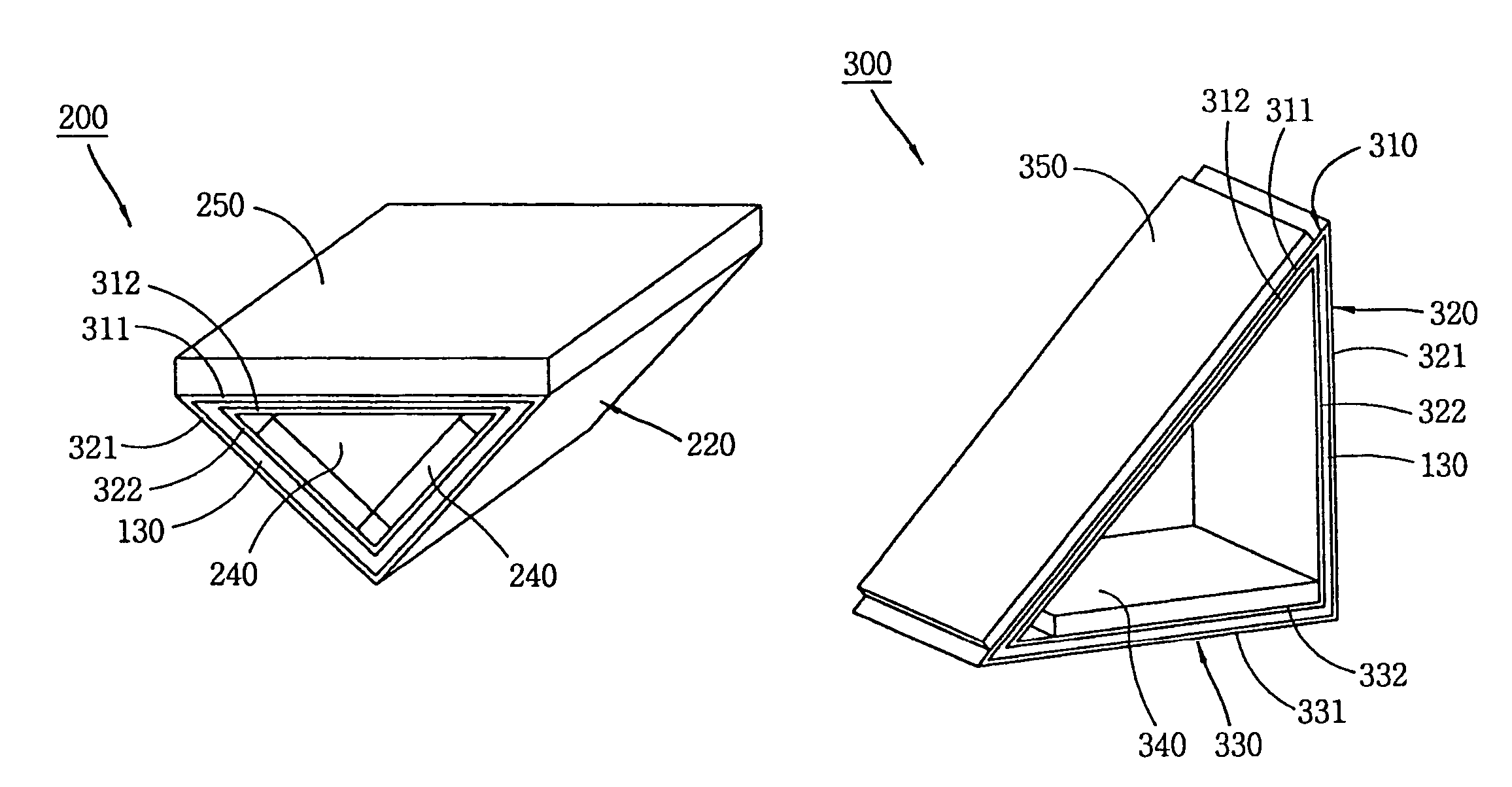
[0049]An explosive reactive armor 300 in accordance with the present invention, as shown in FIG. 7, is also formed by modifying the basic arrangement of the explosive reactive armor 100 with the momentum transfer mechanism. In the explosive reactive armor 300, the form of the explosive reactive armor is arranged as a right triangle (the angle between first and second rear plate members 320 and 330 is about 80° to 100°), and flying elements 340 and 350 are added only onto the front plate member 310 and the second rear plate member 330 parallel with the ongoing direction of the threat 2. In such construction, because the front surface flying element 350 is oblique with respect to the ongoing direction of the threat 2, a dynamic plate thickness of the flying elements 310 and 350 can be increased, while the second rear plate member 330 travels transversely to the ongoing direction of the threat according to the propagation of the detonation wave to apply a momentum in a transverse direc...


PUM


Abstract

Disclosed is an explosive reactive armor with a momentum transfer mechanism by developing a new protection mechanism in which a momentum transfer mechanism by detonation of a reactive material is integrated with a thickness increase mechanism. In this explosive reactive armor with the momentum transfer mechanism, a flying element always travels with a vertical angle or a slant angle with respect to an ongoing direction of the threat such that a momentum of the flying element is transferred to the threat effectively. As a result of this, shear force is induced over an entire length of the threat and thus the threat can be destroyed. Therefore, a protection effect can always be achieved regardless of an impact angle of the threat. Also, a protection capability can be achieved even in case of a vertical impact which is the most vulnerable case for the existing explosive reactive armor.

Description

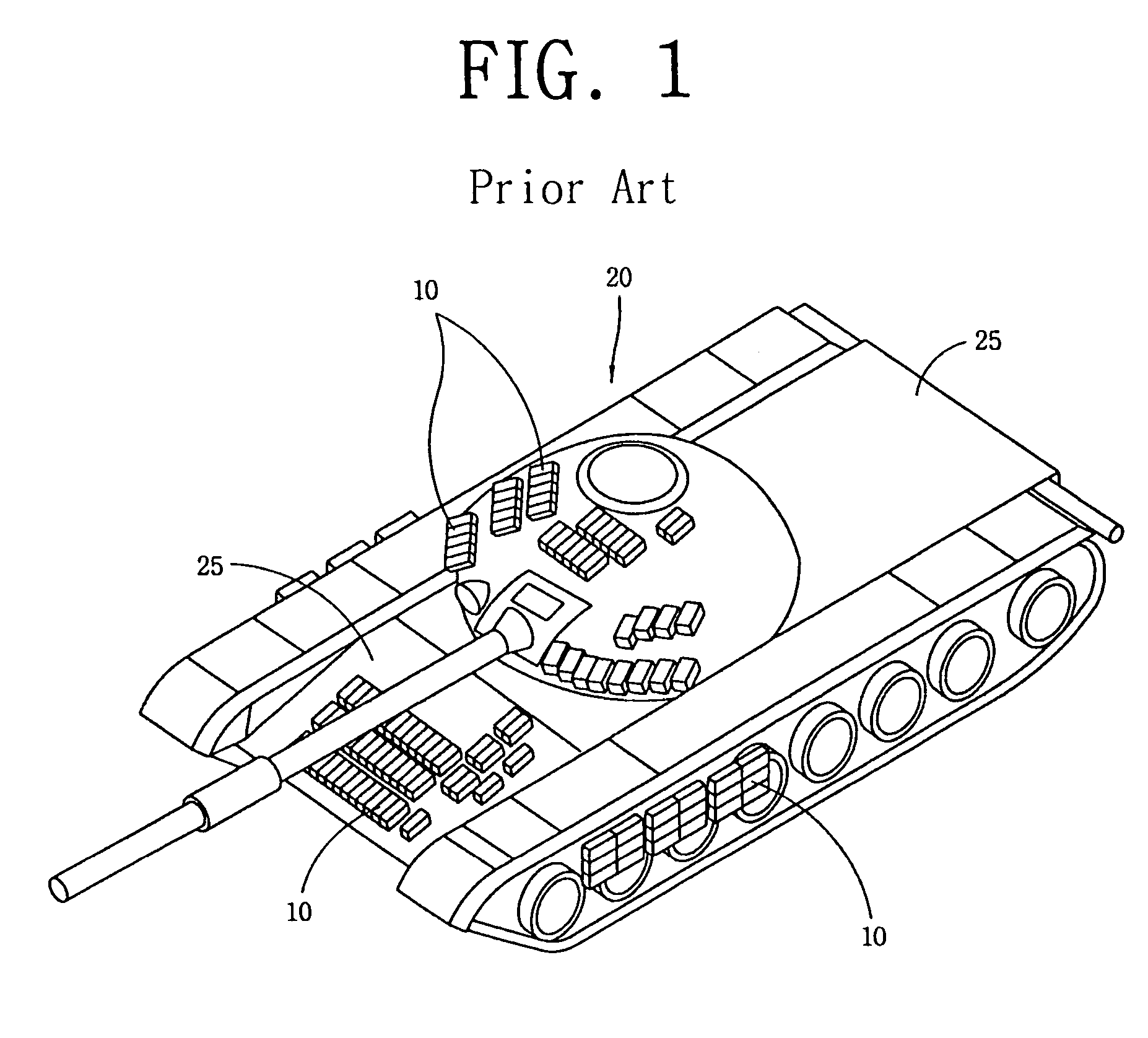
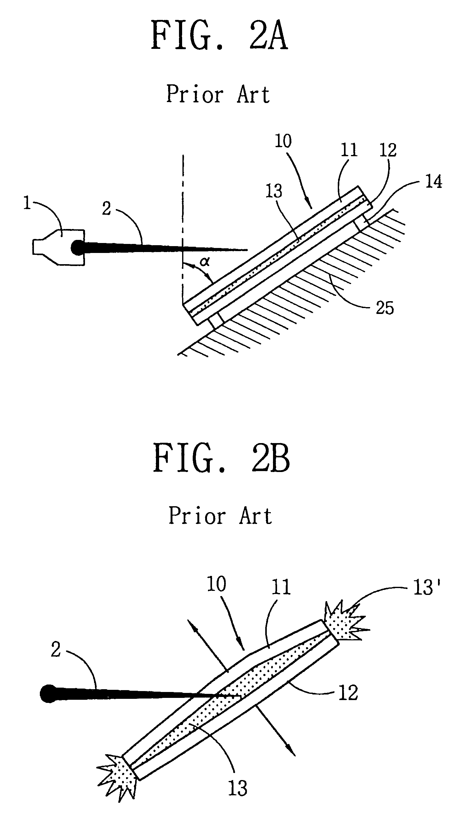
BACKGROUND OF THE INVENTION[0001]1. Field of the Invention[0002]The present invention relates to an explosive reactive armor for use in combat vehicles, and particularly, to an explosive reactive armor with a momentum transfer mechanism which is capable of providing a protection effect regardless of the incident angle of a threat including a right angle of incident threat.[0003]2. Description of the Prior Art[0004]In general, explosive reactive armor, as shown in FIG. 1, is a protection mechanism fixed to the exterior of a combat vehicle (e.g., an armored vehicle) by bolting or other means, for protecting the combat vehicle from an external threat such as the penetrator or jet of a warhead or the like. Referring to FIG. 2A, a prior explosive reactive armor 10 is installed at an outer surface 25 of the combat vehicle so as to form a slope angle inclined (α) with respect to the vertical and includes a reactive material 13 such as a high explosive charge filled within a casing between ...

Claims


Application Information

Patent Timeline
Patent Type & Authority Patents(United States)
IPC IPC(8): F41H5/007
CPCF41H5/007F41H7/04F41H5/02
Inventor SEO, YONGSEOKKIM, JEONG-TAECHOI, CHANG
Owner AGENCY FOR DEFENSE DEV
Why Eureka
Eureka Blog
Learn More