
Method and system for creating a textured surface on an implantable medical device

a medical device and surface technology, applied in the field of forming surface features of implantable medical devices, can solve the problems of disengagement from the stent, peeling, cracking, and peeling of the coating, and achieve the effect of increasing the amount of therapeutic substances

Inactive Publication Date: 2009-05-26
ABBOTT CARDIOVASCULAR
View PDF16 Cites 93 Cited by
  • Summary
  • Abstract
  • Description
  • Claims
  • Application Information

AI Technical Summary

Benefits of technology

The present invention provides an implantable medical device that can deliver therapeutic substances from a coating, which is better retained and allows for greater amounts of therapeutic substances to be delivered. The device can be prepared by applying electric discharges to a designated region of the surface, which causes the surface to be rough and allows for more coating to adhere to the surface, improving coating retention. The device can be a stent or graft with pre-formed depots in the surface. The technical effects of the invention include improved therapeutic substance delivery and better mechanical hold for the coating.

Problems solved by technology

Following the PTCA procedure, however, damage to the arterial lining can potentially cause re-occlusion of the artery, due to thrombosis, restenosis, or collapse of the arterial walls.
An obstacle often encountered with the use of stent coatings is poor adhesion of the polymeric coating to the surface of a stent.
Also, when a coated stent is expanded in situ, the distortion the stent undergoes as it expands can cause the coating to peel, crack, or tear, and disengage from the stent.
Poor adhesion of the coating material can promote thrombosis and restenosis, by providing additional surfaces for platelets and other blood components to adhere.
Additionally, poor adhesion and loss of the coating also leads to loss of a significant amount of the drugs to be delivered from the coating.
Another technical challenge in using stent coatings to deliver drugs is loading enough drug onto the stent, so that an effective amount of the drug or drug combination is delivered to the treatment site.
However, increasing the thickness of a stent coating can be difficult, particularly if the coating does not adhere well to the stent material.
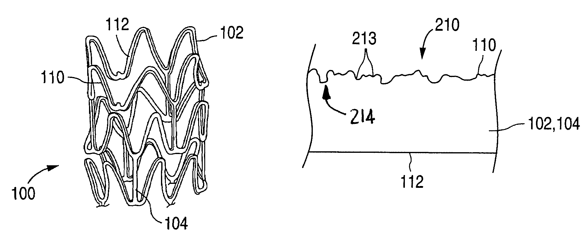
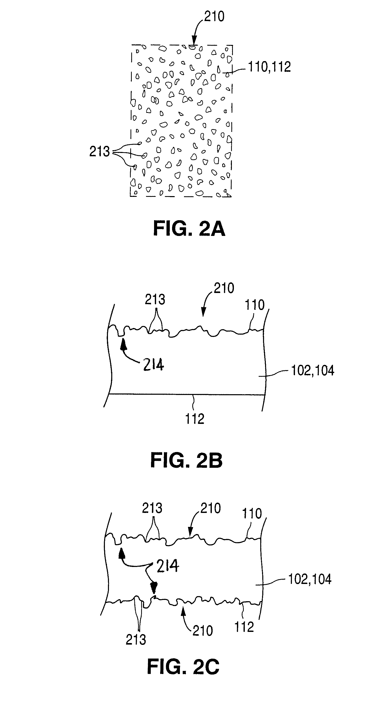
When the electric discharges strike the surface of the implantable medical device, material that forms the surface of the device vaporizes, leaving pits or voids, which cause the surface to be rough.
The resulting arcs pit the surface of the device.

Method used


Image

  • Method and system for creating a textured surface on an implantable medical device
  • Method and system for creating a textured surface on an implantable medical device
  • Method and system for creating a textured surface on an implantable medical device

Examples


Embodiment Construction

Implantable Medical Device

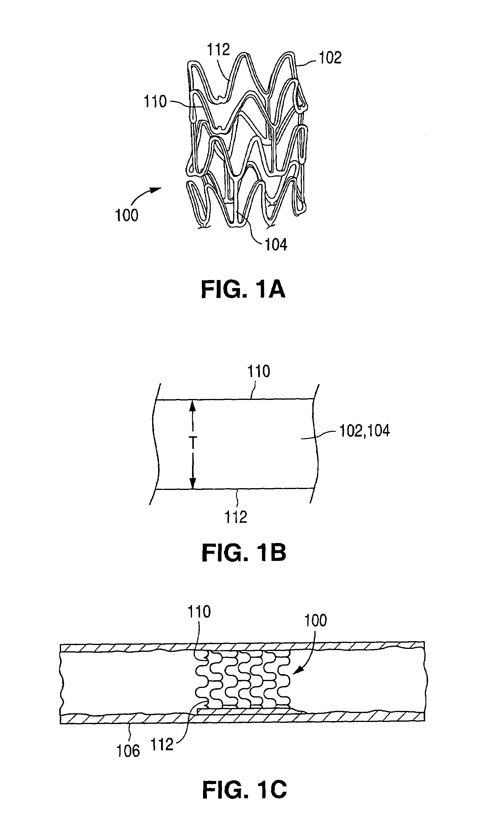
[0032]The present invention provides a method for treating the surface of an implantable medical device, such as a stent or graft, which are often referred to as endoprostheses. Beyond stents and grafts, however, other implantable medical devices, such as artificial joints, bones, pacemakers, and the like, may be made in accordance with the methods of the present invention and used for drug delivery. In the discussion below, the example of a stent is provided. Practitioners will appreciate, however, that the methods and structures of the present invention are not limited to a stent, but rather extend to all implantable devices having a metallic surface upon which a coating can be deposited.

[0033]FIGS. 1A-1C illustrate an exemplary stent 100 in accordance with one embodiment of the present invention. Exemplary stent 100 is a patterned tubular device that includes a plurality of radially expanding cylindrical struts 102 disposed generally coaxially. Connectin...


PUM

PropertyMeasurementUnit
thicknessaaaaaaaaaa
sizeaaaaaaaaaa
sizeaaaaaaaaaa

Abstract

A method for forming an implantable medical device, such as a stent, is provided, in which electric discharges are applied to a metal surface of the implantable medical device. The electric discharges pit the surface. The pitted surface improves retention of a coating on the device and increases the amount of coating that can be carried by the device. An electric discharge machining process is described for applying electric discharges to the surface of the implantable medical device or portion thereof.

Description

CROSS REFERENCE[0001]This is a divisional application of U.S. Ser. No. 09 / 752,497, which was filed on Dec. 27, 2000 now U.S. Pat. No. 6,913,617.BACKGROUND OF THE INVENTION[0002]1. Field of the Invention[0003]This invention relates generally to methods for forming surface features of implantable medical devices. More particularly, the present invention is directed to methods of using electric discharges to roughen the surface of implantable medical devices, such as stents and grafts, with numerous pits.[0004]2. Description of the Background[0005]Percutaneous transluminal coronary angioplasty (PTCA) is a procedure for treating heart disease. A catheter assembly having a balloon portion is introduced into the cardiovascular system of a patient via the brachial or femoral artery. The catheter assembly is advanced through the coronary vasculature until the balloon portion is positioned across the occlusive lesion. Once in position across the lesion, the balloon is inflated to a predeterm...

Claims


Application Information

Patent Timeline
Patent Type & Authority Patents(United States)
IPC IPC(8): A61F2/06A61F2/00B23H9/00
CPCB23H9/008A61F2/06A61F2250/0068Y10S623/901
Inventor REISS, PAUL
Owner ABBOTT CARDIOVASCULAR
Learn More