
System architecture for a power distribution network and method of operation

a technology of system architecture and power distribution network, applied in the direction of instruments, data switching details, liquid/fluent solid measurement, etc., can solve the problem of extremely limited space for additional functionality of the port connector module, and achieve the effect of eliminating digital circuitry and functionality, reducing manufacturing costs, and reducing manufacturing costs

Active Publication Date: 2009-05-19
TEXAS INSTR INC
View PDF10 Cites 8 Cited by
  • Summary
  • Abstract
  • Description
  • Claims
  • Application Information

AI Technical Summary

Benefits of technology

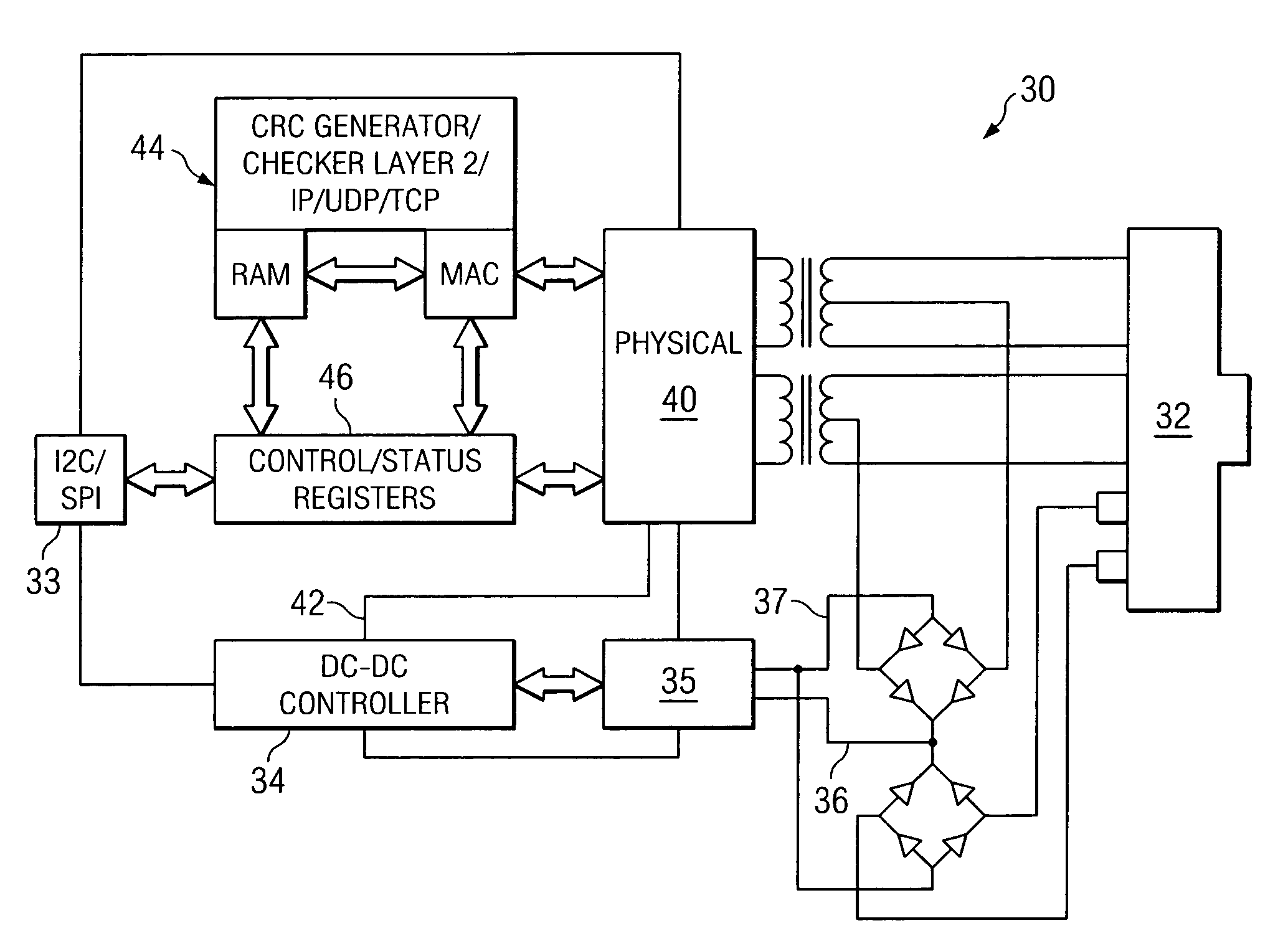
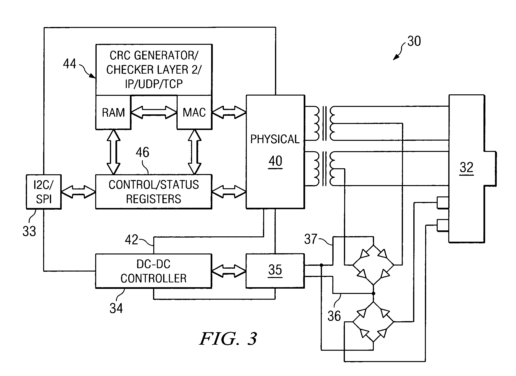
The present invention provides a system architecture and method of operation that separates analog and digital features and functionality between power control devices and communication link devices in a distributed network environment. This separation of analog and digital features or functionality between the PHY controller and power controller eliminates redundancy and reduces space use in the port module for providing power. The PSE and Ethernet PHY transceiver system architecture is integrated together to reduce cost over a separate component architecture. The power controller includes analog to digital converters and digital to analog converters that transform analog information into digital form and vice versa, which can be transferred over the high speed link. The power controller can also handle control functions for the POE power controller including response to transient conditions and implementing sophisticated algorithms for managing network power. The complementary PHY and power controller chip set or integrated circuit board can be simplified and has reduced costs.

Problems solved by technology

Accordingly, the port connector module has extremely limited space for additional functionality that would be desired for the realization of a number of POE or other applications, for example.

Method used


Image

  • System architecture for a power distribution network and method of operation
  • System architecture for a power distribution network and method of operation
  • System architecture for a power distribution network and method of operation

Examples


Embodiment Construction

[0022]Referring now to FIG. 1 a POE port module is illustrated generally as module 10. Module 10 includes a number of ports 12 for receiving cabling connectors, such as RJ45 connectors, for delivering distributed power over a network, such as POE. Each port 12 has associated electronic devices in module 10 to support POE and network communication functions. Each port 12 has an associated printed circuit board (PCB) 14 that handles functions including LED lighting indications or LED drivers and magnetic control of port connections, for example. PCBs 14 may also include capacitors and resistive elements to meet electronic operation requirements or ratings, such as in the range of 2 kV. In addition, each PCB 14 can have optical coupling components for signal isolation from electronic noise. Vertical PCBs 14 can also include connections for light pipes to transfer LED output to a front of ports 12. PCBs 14 can also include power components and electrical connections for supplying POE.

[0...


PUM


Abstract

Digital and analog functionality are separated and optimized in an Ethernet port architecture to free port circuit space for additional desired functionality. A power controller and physical link controller for the port share a high speed communication link to transfer information and control instructions from one to the other. The physical link controller provides digital functionality and processing capabilities that can generate power control instructions sent to the power controller over the high speed link. The power controller provides analog functionality for controlling the power supplied to the network connection and transfers power related information to the physical link controller over the high speed communication link and receives control instructions through a digital interface. The separation of digital of analog functionality simplifies the power control circuitry, removes redundancy, and frees valuable circuit board space for other desired functionality.

Description

CROSS REFERENCE TO RELATED APPLICATIONS[0001]N / ASTATEMENT REGARDING FEDERALLY SPONSORED RESEARCH OR DEVELOPMENT[0002]N / ABACKGROUND OF THE INVENTION[0003]1. Field of the Invention[0004]The present invention relates generally to a system architecture for a power distribution network and a method of operating the architecture. The present invention relates more specifically to a transceiver and control circuit architecture for power over Ethernet and a method for providing and operating the architecture.[0005]2. Description of Related Art[0006]The development of sophisticated networks for transferring information has driven a number of technologies including the provision of power over network connections. For example, a network connected device for transferring information over the network may receive power from the network so that alternate power sources for the devices are not necessary. A typical advantage associated with providing power over a network is that a user can physically...

Claims


Application Information

Patent Timeline
Patent Type & Authority Patents(United States)
IPC IPC(8): G06F1/00
CPCH04L12/10
Inventor HEMMAH, STEVEN M.NEIDORFF, ROBERT A.BEARFIELD, JONATHAN M.
Owner TEXAS INSTR INC
Learn More