
Charging system for legged walking robot

a charging system and walking robot technology, applied in electric vehicles, manufacturing tools, transportation and packaging, etc., can solve the problems of losing the joint motor for retaining positions, inability to maintain standing posture, etc., and achieve the effect of increasing the current of the battery

Inactive Publication Date: 2009-04-28
HONDA MOTOR CO LTD
View PDF12 Cites 103 Cited by
  • Summary
  • Abstract
  • Description
  • Claims
  • Application Information

AI Technical Summary

Benefits of technology

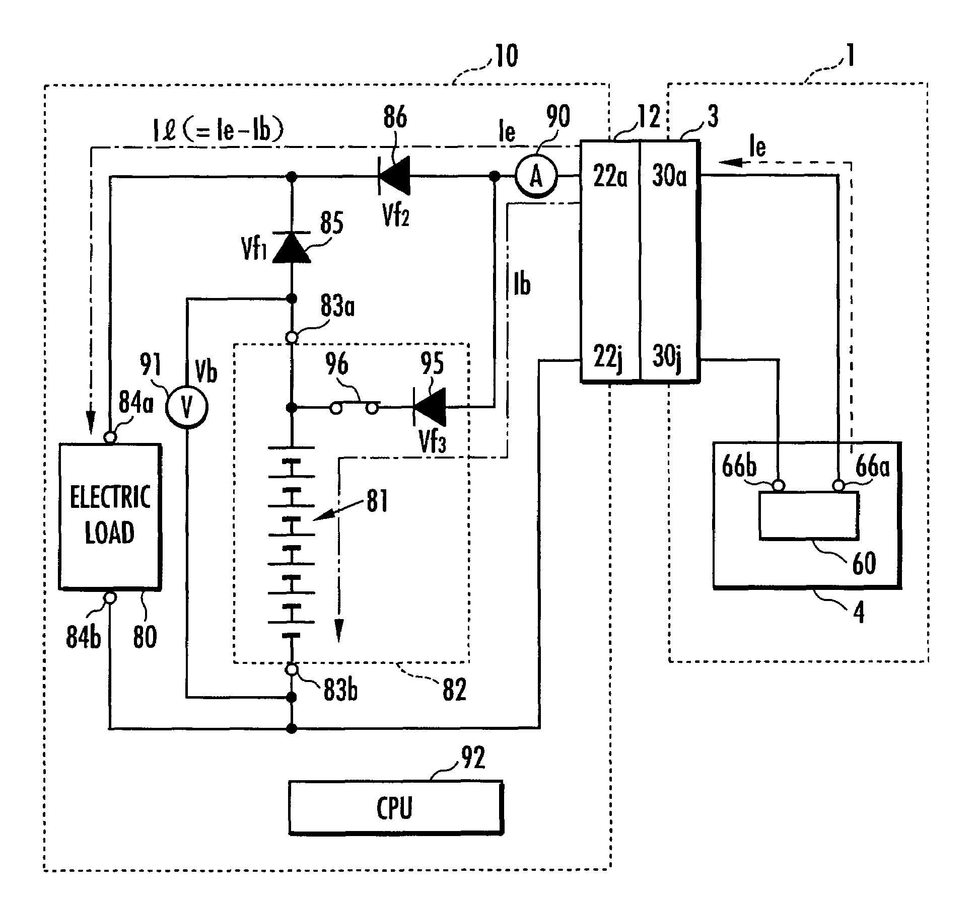
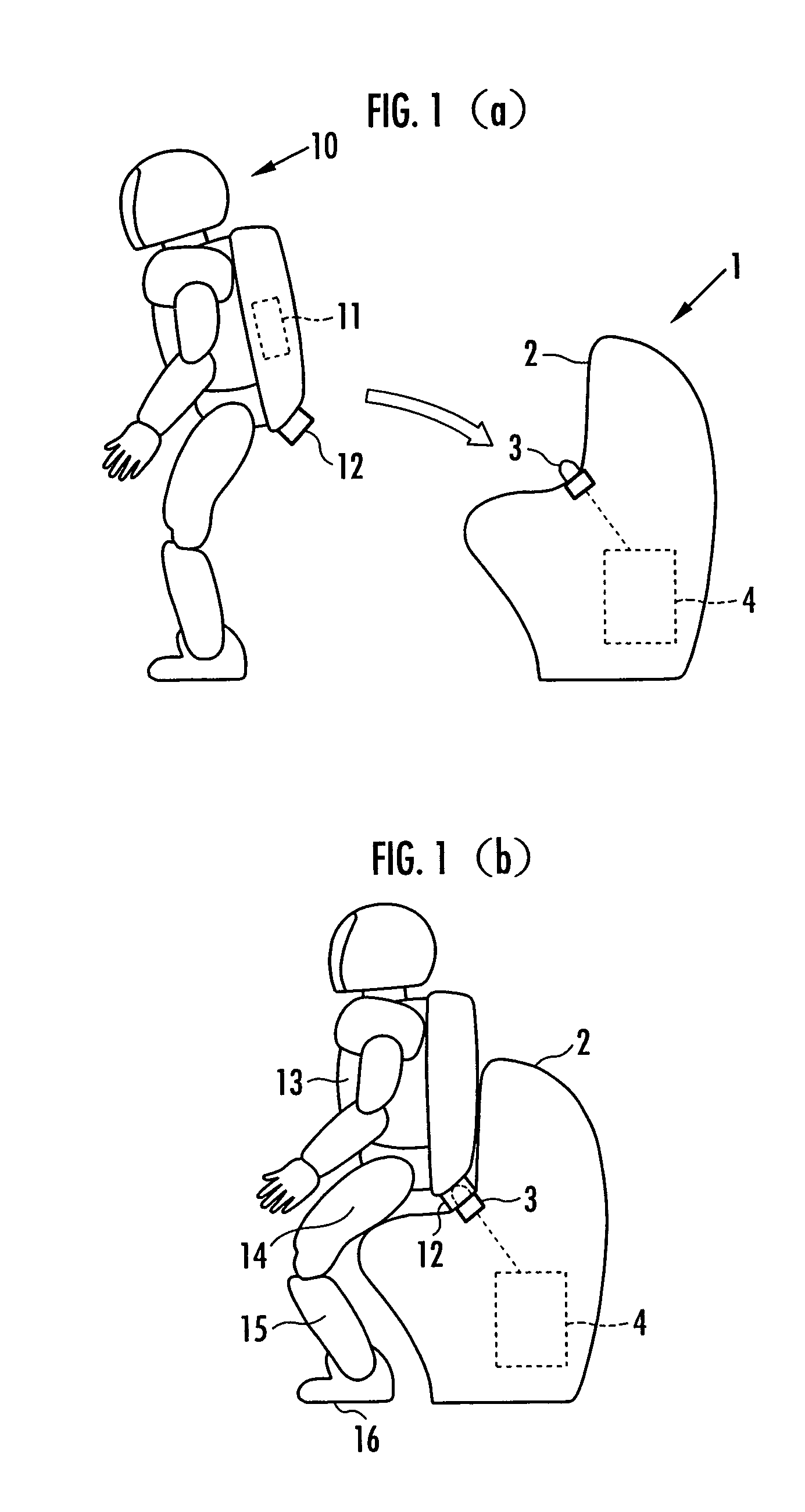
[0007]Accordingly, it is an object of the present invention to provide, with a simple construction and at low cost, a charging system capable of supplying charging current to a battery of a legged walking robot while maintaining the supply of required current to an electric load of the legged walking robot by an external power source connected to the legged walking robot.

Problems solved by technology

In the case of a legged walking robot using a battery as its power source, if the electric power supplied to joint motors of legs is cut off while charging the battery, then the action of each joint motor for retaining positions is lost, making it impossible to maintain a standing posture.

Method used


Image

  • Charging system for legged walking robot
  • Charging system for legged walking robot
  • Charging system for legged walking robot

Examples


first embodiment

[0060]In the first embodiment described above, the current breaker switch 96 for cutting off the charging path from the charger 1 to the battery 11 of the biped walking robot 10 has been provided to open the current breaker switch 96 upon completion of charging. The advantages of the present invention, however, can be obtained even if the current breaker switch 96 is not provided.

[0061]In the embodiment, the power receiving connector 12 is detached from the power feeding connector 3 after it is detected that a current detected by the current sensor 90 has reduced after the current breaker switch 96 is opened upon completion of the charging of the battery 11. However, the advantages of the present invention can be obtained even if such detection is omitted.

second embodiment

[0062]As in the present invention shown in FIG. 6A, a charger 1a may be provided with a posture retainer 2a against which the biped walking robot 10 leans in a half-sitting posture, and the power receiving connector 12 of the biped walking robot 10 and the power feeding connector 3 of the charger 1a may be connected while the biped walking robot 10 is leaning against the posture retainer 2a in the half-sitting posture.

[0063]As in yet another embodiment of the present invention shown in FIG. 6B, a charger 1b may be provided with a posture retainer 2b against which the biped walking robot 10 leans in a standing posture, and the power receiving connector 12 of the biped walking robot 10 and the power feeding connector 3 of the charger 1a may be connected while the biped walking robot 10 is leaning against the posture retainer 2b in the standing posture.

[0064]In the aforesaid embodiments, the power receiving connector 12 has been provided on the back of the biped walking robot 10; howev...


PUM


Abstract

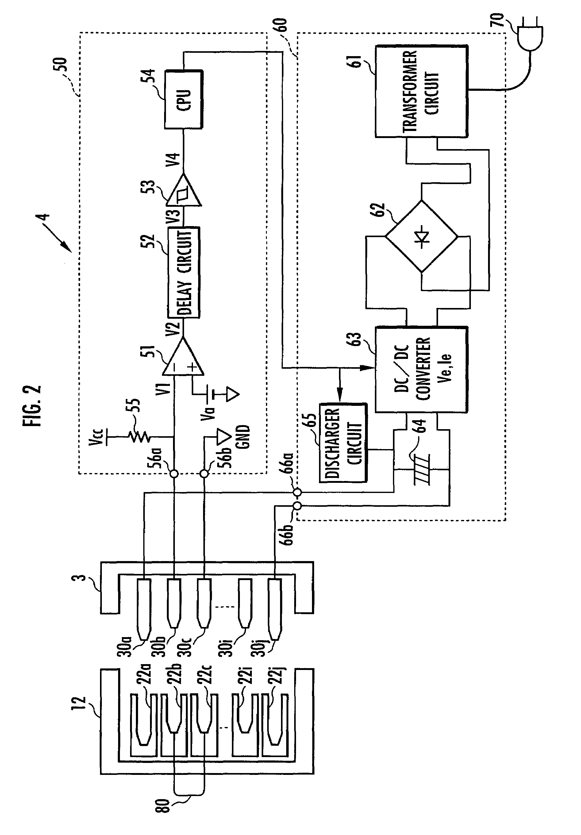
An inexpensive charging system with a simple construction can supply charging current to a battery of a legged walking robot while maintaining the supply of required current to an electric load of the legged walking robot by an external power source. The charging system includes a connection circuit having a first, a second diode, a third diode, and a circuit that brings various negative electrode and a negative input terminal of the electric load into conduction, and an output electric power controller that sets an output voltage of the external power source to be higher than a total voltage of a voltage across electrodes of the battery when the battery is fully charged and a forward voltage of the third diode, while setting a current of the external power source that can be output to be larger than a required current of the electric load.

Description

BACKGROUND OF THE INVENTION[0001]1. Field of the Invention[0002]The present invention relates to a system for charging a battery provided in a legged walking robot by connecting an external power source to the legged walking robot.[0003]2. Description of the Related Art[0004]As a system for charging a battery provided in a robot, there has been known, for example, an industrial robot adapted to detect an absolute position of a movable part by an encoder, a backup battery being provided therein for uninterruptedly supplying current to the encoder so as to retain the data on the absolute position detected by the encoder even when the power line of the industrial robot is turned off (refer to, for example, Japanese Unexamined Patent Application Publication No. 5-228885).[0005]There has been also known a mobile robot adapted to move among a plurality of work stations to carry out predetermined operations. While the mobile robot is halted at a work station, an external AC power source an...

Claims


Application Information

Patent Timeline
Patent Type & Authority Patents(United States)
IPC IPC(8): H02J7/00
CPCB25J19/005H02J7/0044H02J7/0068H02J7/00H02J7/04
Inventor KOYANAGI, TAKUROKANEKO, SATOSHI
Owner HONDA MOTOR CO LTD
Learn More