
Image recording method and image recording apparatus

a recording method and image technology, applied in the field of image recording methods and image recording apparatuses, can solve problems such as one-dimensional non-uniformity, linear non-uniformity in the conveyance direction of recording paper, and easy to be noticed linear non-uniformity, etc., to achieve the effect of improving image quality and improving image quality

Inactive Publication Date: 2009-04-28
FUJIFILM CORP
View PDF7 Cites 14 Cited by
  • Summary
  • Abstract
  • Description
  • Claims
  • Application Information

AI Technical Summary

Benefits of technology

[0032]According to this aspect of the invention, it is possible to reduce non-uniformity of density, such as linear non-uniformity, by compensating the droplet ejection rate signal in a suitable fashion.
[0045]As described above, according to the image recording method and apparatus relating to the present invention, it is possible to satisfactorily eliminate non-uniformity of density, such as linear non-uniformity, by compensating the droplet ejection rate signal.

Problems solved by technology

In an inkjet recording apparatus of this kind, there is a possibility that one-dimensional non-uniformity may arises due to errors in the print characteristics (ejection characteristics) of each nozzle.
Therefore, linear non-uniformity in the conveyance direction of the recording paper is readily noticeable.
As a result, linear non-uniformity appears on the recording paper 904, as shown in FIG. 29B, and this might become a problem in terms of image quality.
In this way, errors in the ejection volume or errors in the landing position in the direction perpendicular to the conveyance direction of the recording paper, lead to band-shaped lines due to the non-uniformity in density in the conveyance direction of the recording paper.
However, in the related art technology described above, it is difficult to completely compensate the linear non-uniformity caused by landing position errors.
However, as described below, in the related art, there is a possibility that it is difficult to compensate non-uniformity of density caused by ink-landing position errors of the nozzles.
Thus the measurement show that there is no non-uniformity in density, and it is therefore difficult to carry out the compensation of the non-uniformity in density.
However, if the sample shown in FIG. 34 is viewed by a human observer with the naked eye, then the displacements are visible as linear non-uniformity.
On the other hand, in the above-described related methods for compensating non-uniformity of density, a problem of this kind is not taken into account, and therefore it is difficult to carry out the sufficient compensation and such methods are not particularly effective with respect to non-uniformity of density arising from landing position errors.
However, the density characteristics obtained in this way fluctuate in a range smaller than the nozzle pitch which is the smallest possible control unit.
Hence, according to the non-uniformity of density compensation methods of the related art such as those described in Japanese Patent Application Publication Nos. 5-69545 and 2004-58282, it is difficult to compensate non-uniformity of density arising from ink-landing position errors as shown in FIG. 34.
Hence, in such cases, it is also difficult to compensate non-uniformity of density which arises from ink-landing position errors.
Therefore this can become a cause of non-uniformity in density.
However, according to the related art described above, this factor is not taken into account, and therefore the compensation may not be complete.

Method used


Image

  • Image recording method and image recording apparatus
  • Image recording method and image recording apparatus
  • Image recording method and image recording apparatus

Examples


Embodiment Construction

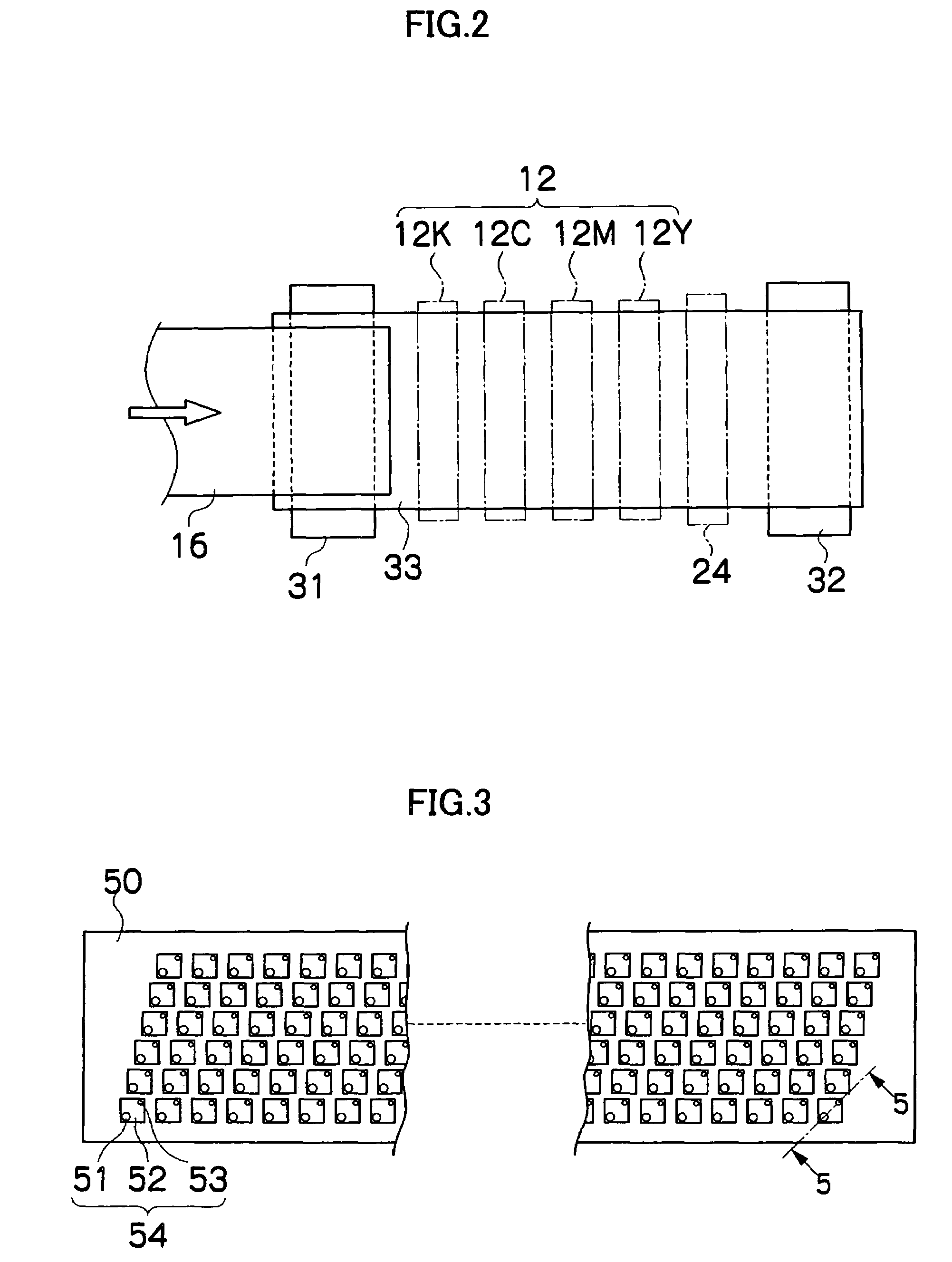
[0084]FIG. 1 is a general schematic drawing of an embodiment of an inkjet recording apparatus which forms an image recording apparatus relating to the present invention.

[0085]As shown in FIG. 1, the inkjet recording apparatus 10 comprises: a print unit 12 having a plurality of print heads (liquid ejection heads) 12K, 12C, 12M, and 12Y for ink colors of black (K), cyan (C), magenta (M), and yellow (Y), respectively; an ink storing and loading unit 14 for storing inks of K, C, M and Y to be supplied to the print heads 12K, 12C, 12M, and 12Y; a paper supply unit 18 for supplying recording paper 16; a decurling unit 20 for removing curl in the recording paper 16; a belt conveyance unit 22 disposed facing the nozzle face (ink-droplet ejection face) of the print unit 12, for conveying the recording paper 16 while keeping the recording paper 16 flat; a print determination unit 24 for reading the printed result produced by the print unit 12; and a paper output unit 26 for outputting image-p...


PUM


Abstract

The image recording apparatus records an image by ejecting ink onto a recording medium from a print head having a plurality of nozzles while moving the print head and the recording medium relatively to each other. The image recording apparatus comprises: a memory device which stores reference density characteristics obtained by measuring a prescribed test pattern formed on the recording medium by means of the nozzles; a density characteristic acquiring device which acquires density characteristics of print areas corresponding to the nozzles; a compensation device which compensates a droplet ejection rate signal of each of the nozzles so that the density characteristics acquired by the density characteristic acquiring device coincide with the reference density characteristics; and a quantization device which quantizes each droplet ejection rate signal compensated by the compensation device.

Description

BACKGROUND OF THE INVENTION[0001]1. Field of the Invention[0002]The present invention relates to an image recording method and an image recording apparatus, and more particularly, to technology for compensating non-uniformity in density caused by an image recording apparatus which records an image by forming dots on a recording medium.[0003]2. Description of the Related Art[0004]As an image recording apparatus, an inkjet recording apparatus (inkjet printer) is known, which comprises an ink ejection apparatus having an inkjet head (recording head) with a plurality of arranged nozzles (ejection elements), for example. According to such an image recording apparatus, images are formed on a recording medium by ejecting ink from the nozzles toward the recording medium while the inkjet head and the recording medium are caused to be moved relatively to each other.[0005]In an inkjet recording apparatus of this kind, there is a possibility that one-dimensional non-uniformity may arises due to...

Claims


Application Information

Patent Timeline
Patent Type & Authority Patents(United States)
IPC IPC(8): B41J2/205
CPCB41J29/393
Inventor CHIWATA, YUHEI
Owner FUJIFILM CORP
Learn More