
System and method for selective transfer of radio frequency power

a radio frequency power and selective transfer technology, applied in the system field, can solve the problems of only charging, leakage impedance, and similar restrictive prior art of the induction charging device, and achieve the effect of increasing the system's tolerance to the detuning of the secondary uni

Inactive Publication Date: 2009-04-21
MOBILEWISE
View PDF4 Cites 376 Cited by
  • Summary
  • Abstract
  • Description
  • Claims
  • Application Information

AI Technical Summary

Benefits of technology

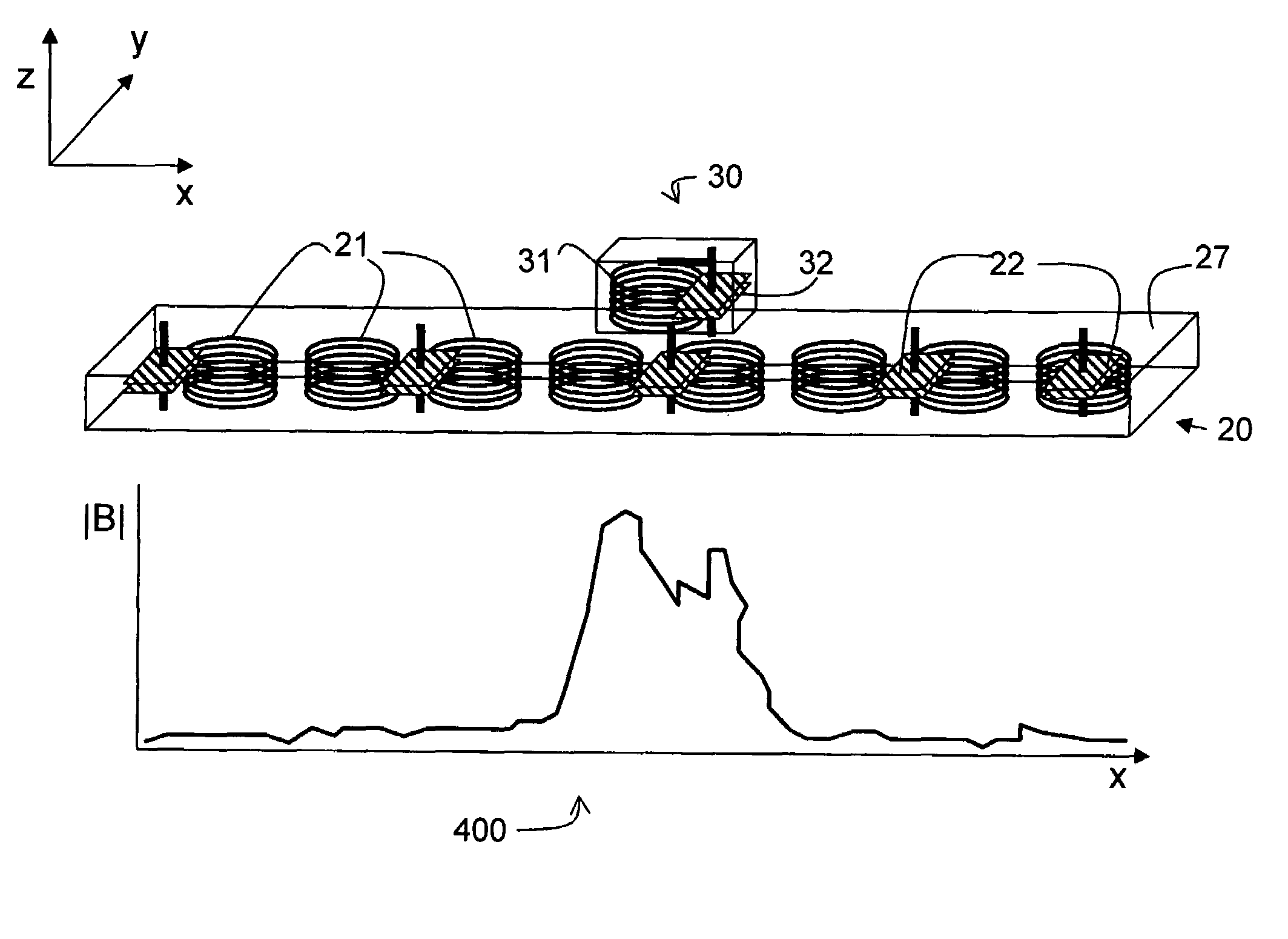
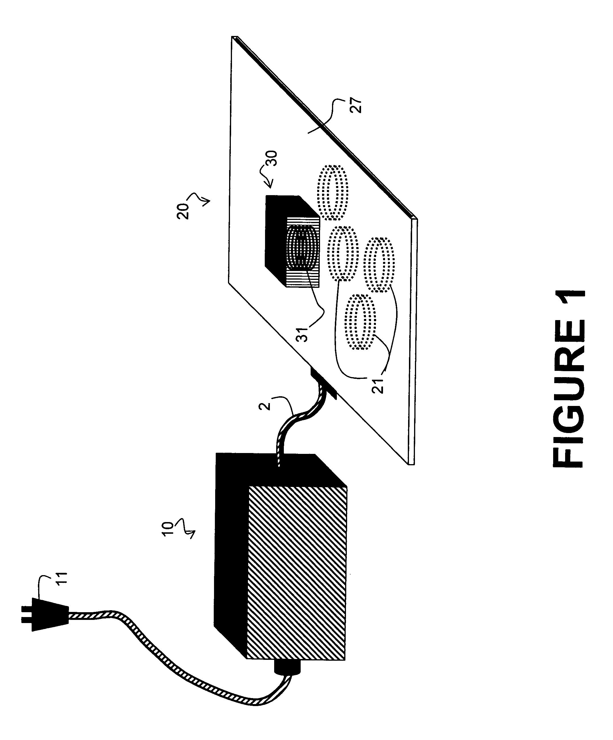
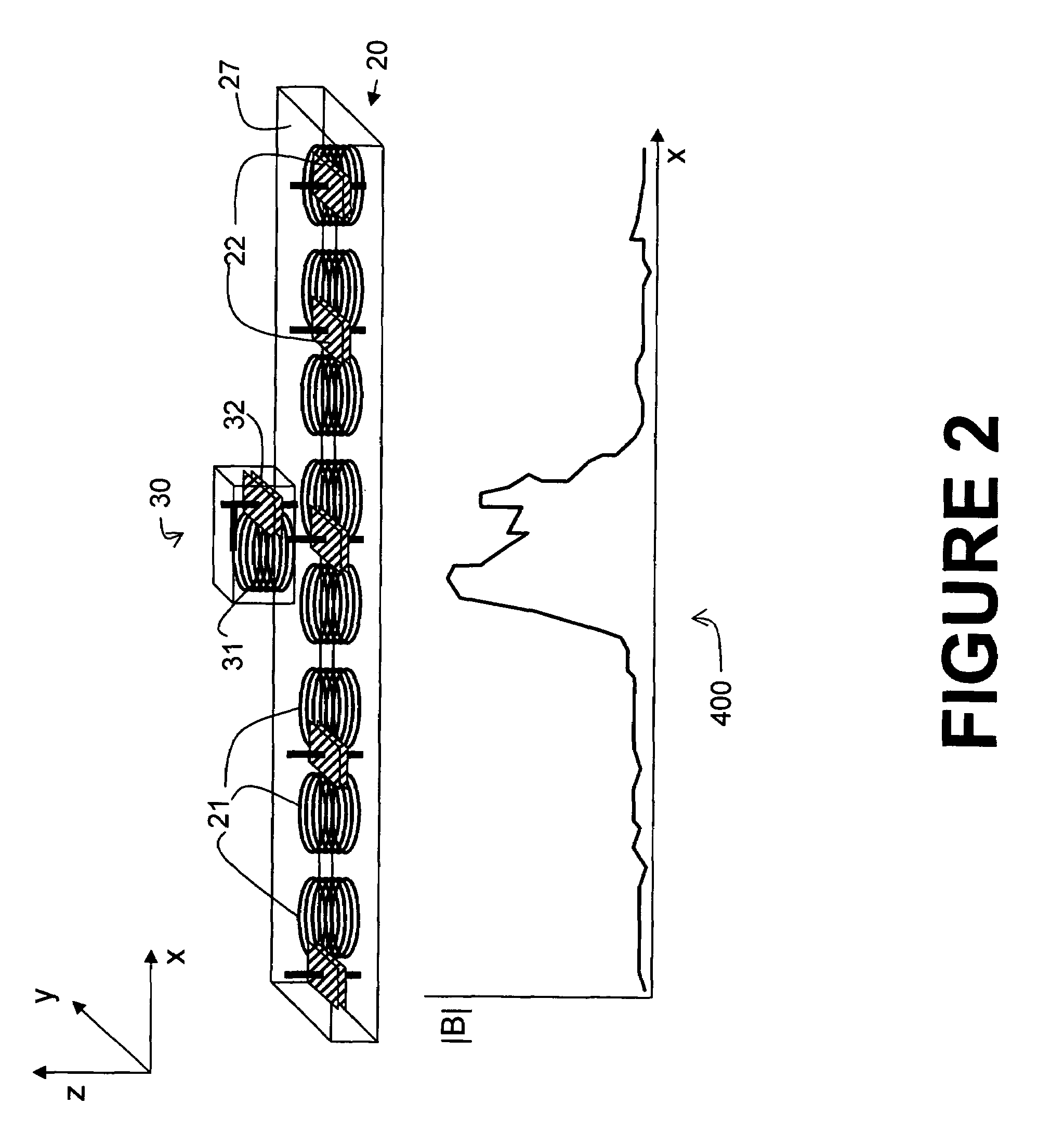
"The patent describes a system for wirelessly transferring electric power using a primary device with a plurality of secondary devices. The primary device has a laminar surface with multiple flat induction coils embedded underneath it. The secondary devices have counterbalance capacitors to reduce interference and electromagnetic interference. The system is unaffected by the presence of conductive objects and can provide uniform power transfer without the need for expensive high magnetic permeability materials. The secondary devices can be coils, capacitors, or other means of inducing current. The primary device can adjust its impedance to match the impedance of the secondary devices. The system can provide power to a large number of secondary devices simultaneously without interfering with each other. The secondary devices can be coils, capacitors, or other means of inducing current. The primary device can also have a sleep mode of operation and can return to normal operation periodically to test the presence of secondary devices. The secondary devices can include a coil or a fixed or programmable controller for regulating the received RF voltage. The system can provide secure and safe power transfer without the need for complex high magnetic permeability materials."

Problems solved by technology

Other induction charging device prior arts are similarly restrictive in the way the primary unit mates with the secondary unit.
For those prior art inventions, the secondary device can only be charged by a dedicated primary device designed for it and charging is only possible if the primary unit is aligned accurately to receive the secondary unit it is designed for.
Hence even a 1% flux leakage will result in leakage impedance that is large enough to practically choke off the primary current.
The requirement for precise alignment presents a major obstacle to the popularity of such devices.
Because the coupling coefficient is so small, very little power actually gets transferred between the primary unit (the interrogator) and the secondary unit (passive RFID tag), hence the energy conversion efficiency is extremely poor.
However, the main purpose of RFID technology is not to provide power transfer, but to enable the interrogator to briefly power up the passive tag's power unit with just enough energy to transmit back the product code information.
Since the intensity of electromagnetic emission is governed by regulatory limits, any device that is capable of generating a large inductive magnetic field profile runs the risk of violating such limits.
In addition, numerous objects can be adversely affected by the presence of a large magnetic field, causing them to either be heated or lose precious stored data.
Despite these advances, this prior art approach suffers from two serious limitations: First, although the magnetic field generated by such approach has a low profile, it does not provide a method to localize the magnetic field around the secondary devices.
Thus, if a metallic object is placed on or near the active area of the primary device, an eddy current will be induced, causing the metal to heat up, with a like effect on the primary unit, which sees the metallic object as an equivalent short, which may lead to irreparable damage to the primary unit.
Hence the concept can't easily be scaled up to large primary devices without exceeding regulatory limits.
Splashpower's devices have also suffered from low energy conversion efficiency.
Since each coil requires a dedicated high frequency switching unit to activate or deactivate, and the central controller unit needs to have an input pin and an output pin for every coil, the complexity increases drastically as the number of primary coils increases.
The drawbacks of the prior art approaches are: First, the power generation devices are typically bulky because of the need to use large inductors and capacitors at such low frequencies as well as the relatively large current requirement.
Second, the high magnetic permeability materials typically have rather large loss tangent, and have nonlinear and hysteretic behaviors at large magnetic flux intensities.
Further, the strong reliance of the prior art approaches on the use of high permeability materials in order to reduce the bulkiness of both the primary and the secondary device means that the only major high magnetic reluctance circuit resides within the air gap between the primary and the secondary devices.
The consequence is that the power transfer decreases rapidly as a function of the air gap, rendering the prior art technologies no better than the prior art solution based on direct electrical contact in their ability to tolerate vertical separation.
Since the lower the driving frequency, the larger the magnetic field required for a given power transfer rate, this means that low frequency inductive power transfer necessarily entails a severe size / power tradeoff, namely, for a given size of the induction coil, there is a power limit.
For audio frequency inductive methods, the power limit for an inductive coil that can fit into a typical cell phone is limited but sufficient to charge a cell phone.
The situation gets worse for larger devices such as a notebook computer which often requires 20-40 times more power to charge its battery but lacks space for a coil large enough for that purpose.
The inability of the majority of prior arts to localize the inductive field presents thorny interference and safety issues, as well as energy conversion efficiency issues.
The danger that is inherent in having stray magnetic flux that can cause metallic objects in its vicinity to heat up, no matter how slowly is a major safety hazard.
An user wearing a ring on his or her finger, or having a metallic implant, is liable to have induced eddy current in and around his / her body.
The electromagnetic interference caused by such stray field can also severely hamper the proper operation of a sensitive electronic device.
Lastly, the presence of nonlocalized field which does not couple to client devices drastically reduce the energy conversion efficiency since the Q factor of the primary coil is not infinity in practice, hence the portion of the current that is responsible for the generation of such stray flux will always have a resistive component.
The larger the unlinked flux, the higher the dissipation loss.
Worse, the magnetic flux does not diminish even in the absence of any client devices in the active vicinity; hence the standby power consumption represents a 100% power loss.
Even though each of the aforementioned problems can be solved in theory, the solutions invariably increase system complexity and drive up cost as well as making the system less reliable and less user-friendly.
Although a metal detector will make the prior art system safer, it significantly limits how the prior art system can be used.
Even then, any small metallic object that accidentally falls on the primary surface will have to be removed, which is clearly a big annoyance.
Worst, if an object such as steel wool whose metallic content is insufficient to trigger the metal detection happens to be on the primary surface, it may still be able to couple to the inductive magnetic field to generate a small Eddy current which causes it to slowly get hot enough to create a fire hazard.
Similarly, if the sensitivity and range of the RFID reader is not properly tuned, it may either be unable to detect an eligible client device and therefore fails to turn on the primary coils, or there may be a client device that is too far to be charged by the primary device and yet close enough to be identified by the RFID reader to prevent the primary device from going to the standby mode.

Method used


Image

  • System and method for selective transfer of radio frequency power
  • System and method for selective transfer of radio frequency power
  • System and method for selective transfer of radio frequency power

Examples


Embodiment Construction

[0052]In the following detailed description of the present invention, certain specific details are set forth to facilitate a thorough understanding of the principle concepts that is contained within the present invention. It will become obvious, however, to those skilled in the art that the present invention may be practiced without those specific details. In other instances, well-known methods, procedures, materials, components and circuitry have not been described in detail to avoid unnecessary obscuring aspects of the present invention. The detailed description focuses only on presenting a self-contained explanation with sufficient depth to cover certain simplified and idealized representations or embodiments of the present invention in order to elucidate the inventive concepts. These descriptions and representations are the means used by those experienced or skilled in the art to concisely and most effectively convey the substance of their work to others skilled in the art.

[0053...


PUM

PropertyMeasurementUnit
RF frequencyaaaaaaaaaa
capacitancesaaaaaaaaaa

Abstract

A system and method is provided for the inductive transfer of electric power between a substantially flat primary surface and a multitude of secondary devices in such a way that the power transfer is localized to the vicinities of individual device coils. The contact free power transfer does not require precise physical alignment between the primary surface and the secondary device and can allow the secondary device or devices to be placed anywhere and in arbitrary orientation with respect to the primary surface. Such power transfer is realized without the need of complex high frequency power switching network to turn the individual primary coils on or off and is completely scalable to almost arbitrary size. The local anti-resonance architecture of the primary device will block primary current from flowing when no secondary device or devices are in proximity to the local RF power network. The presence of a tuned secondary device detunes the local anti-resonance on the primary surface; thereby enable the RF power to be transferred from the local primary coils to the secondary device. The uniformity of the inductive coupling between the active primary surface and the secondary devices is improved with a novel multi-pole driving technique which produces an apparent traveling wave pattern across the primary surface.

Description

FIELD OF INVENTION[0001]One embodiment described herein relates to a system and method for efficient and safe transfer of electrical power without needing conductive contacts.BACKGROUND OF THE INVENTION[0002]Contact free power transfer has been around for a long time. A case in point is the transformer which converts high voltage AC power into low voltage AC power and vice versa through a shared inductive magnetic field. The inductive magnetic filed is generated by the primary coil which induces an electromotive force that propels electrons in the secondary conducting coil with the aid of a high magnetic permeability material core. There are no direct electrical conductive contacts between the primary and the secondary coils. A modern example of a transformer is the Braun Oral B toothbrush, which relies on the external casing of the toothbrush base to guide the toothbrush to mate with the internal shape of the charger module, thus allowing the primary coil, the secondary coil, and t...

Claims


Application Information

Patent Timeline
Patent Type & Authority Patents(United States)
IPC IPC(8): H01M10/46
CPCH02J5/005G01V3/104H02J50/402H02J7/00308H02J50/005H02J50/12H02J50/70
Inventor LEE, YEECHUNSU, VICTOR
Owner MOBILEWISE
Learn More