Electromagnetic friction clutch

a friction clutch and electromagnet technology, applied in the direction of fluid clutches, clutches, non-mechanical actuated clutches, etc., can solve the problems of friction clutch not being suitable in practice, clutches not being usable for applications, and still relatively long time for switching friction clutches between engaged (“adhering”) and disengaged (“slipping”) positions

Inactive Publication Date: 2009-04-21
SCHAEFFLER TECH AG & CO KG
View PDF11 Cites 10 Cited by
  • Summary
  • Abstract
  • Description
  • Claims
  • Application Information

AI Technical Summary

Benefits of technology

[0027]It is appropriate for the position transducer to be configured as a ring element that is positioned approximately concentrically to an axis of rotation of at least one clutch part. The measu

Problems solved by technology

The friction clutch has the disadvantage that the time for switching the friction clutch between the engaged (“adhering”) and the disengaged (“slipping”) positions is still relatively long.
The friction clutch is therefore not suitable in practice for applications in which quick engagement

Method used


Image

  • Electromagnetic friction clutch
  • Electromagnetic friction clutch
  • Electromagnetic friction clutch

Examples


Embodiment Construction

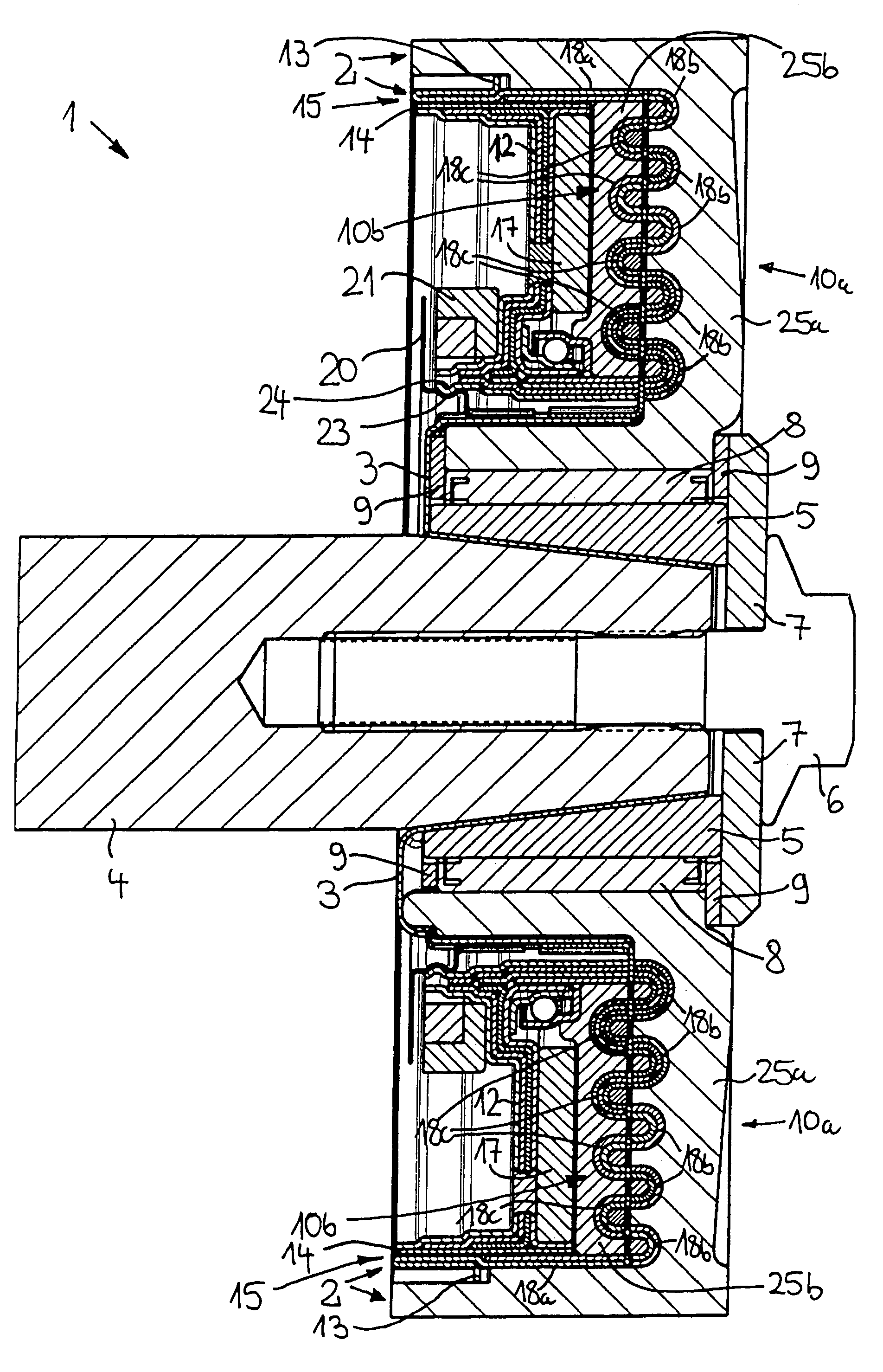
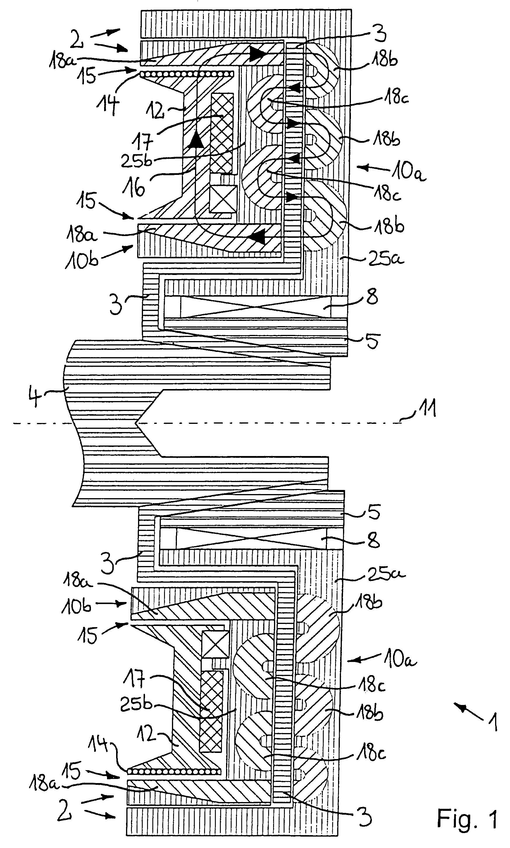
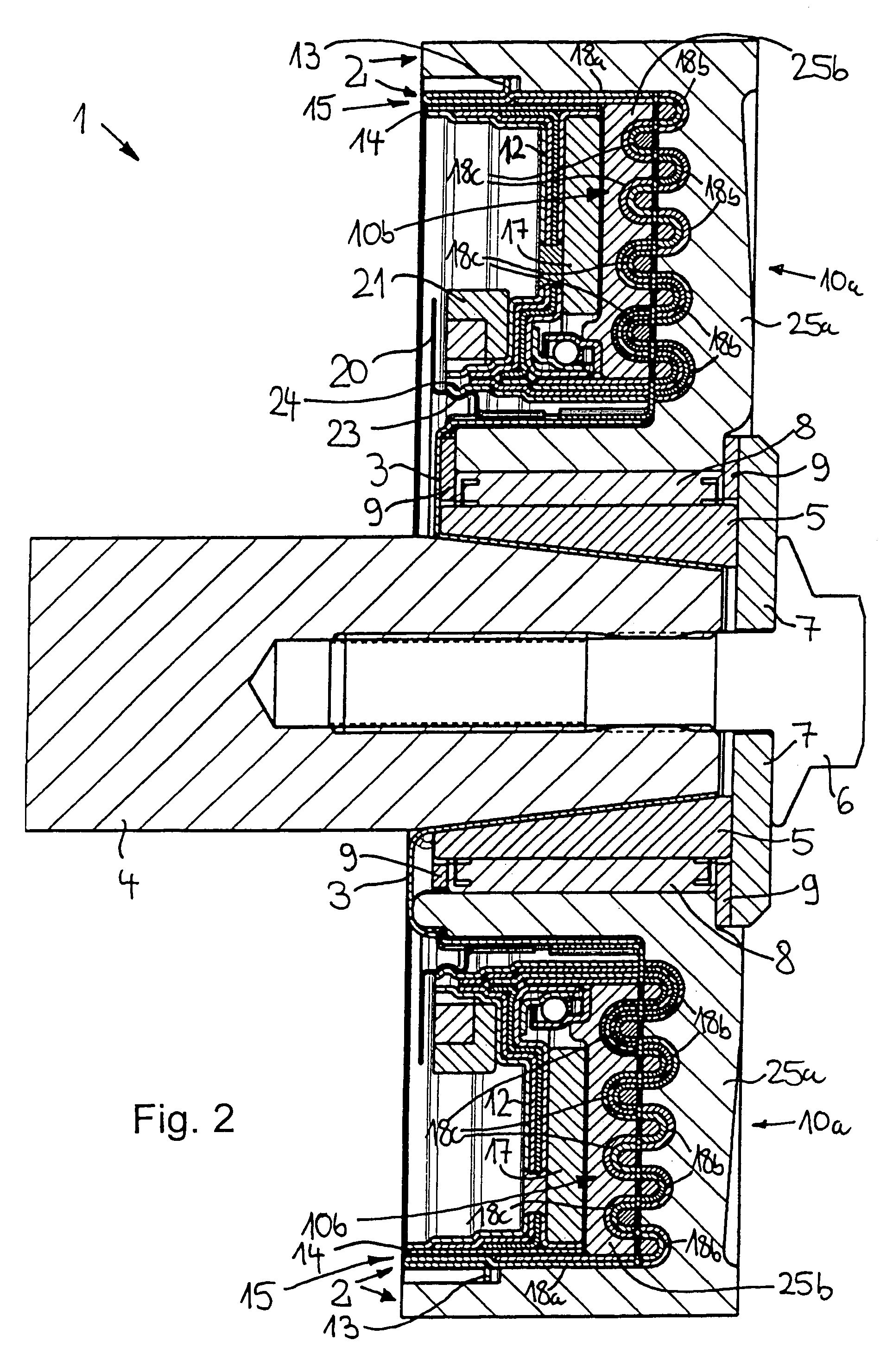
[0033]An electromagnetic friction clutch designated throughout as 1 has a first clutch part 2 and a second clutch part 3 rotatably mounted relative thereto, which are positioned on a shaft 4, which may be the camshaft of an internal combustion engine, for example. FIGS. 1 and 2 show that second clutch part 3 is connected to shaft 4 in a rotationally fixed manner via a conical sleeve 5. The inner conical surface of conical sleeve 5 is clamped against an outer conical surface of shaft 4 by a central screw 6 (FIG. 2), which is screwed into a threaded hole bored in an end of shaft 4. FIG. 2 shows that a plain washer 7 is situated between central screw 6 and the end of the conical sleeve. First clutch part 2 is connected with shaft 4 so that it is able to rotate around the axis of shaft 4, via a first roller bearing 8 positioned on the outer circumference of conical sleeve 5 and having needle rollers. Positioned axially on both sides of roller bearing 8 in the exemplary embodiment accord...


PUM


Abstract

An electromagnetic friction clutch has at least two clutch parts that are mounted so as to be rotatable relative to each other and movable toward and away from each other and that touch each other with a contact force in the position of use. The clutch parts are located in a magnetic circuit, which is guided in the clutch parts in a soft magnetic material in sheet form. Positioned in the magnetic circuit is an electromagnet having a soft magnetic core and a coil. The magnetic circuit has air gaps between the soft magnetic core and at least one of the clutch parts. The flux density in the magnetic circuit, and thus the contact force, is modifiable via the current applied to the coil. The magnetic flux changes at least ten flux crossover points one after the other in the direction of flow between the clutch parts. The cross section of the magnetic flux in at least one air gap is at least five times greater than the smallest flux cross section in the soft magnetic material.

Description

[0001]This claims the benefit of German Patent Application DE 103 15 823.5, filed Apr. 7, 2003 and hereby incorporated by reference herein.BACKGROUND INFORMATION[0002]The present invention relates to an electromagnetic friction clutch having at least two clutch parts that are mounted so as to be rotatable relative to each other and may be pressed against each other by the magnetic force of a magnetic circuit guided in the clutch parts in a soft magnetic material, at least one electromagnet being situated in the magnetic circuit to change the magnetic flux in the clutch parts.[0003]A friction clutch of this sort for a lawnmower is known from European Patent Document 0 537 022 B1. The clutch has a first clutch part, configured in a cup-shaped manner and positioned on a drive shaft of a motor, and a second clutch part, parallel to the floor of the cup-shaped clutch part and having an approximately disk-shaped configuration. The second clutch part is joined by leaf springs in a rotation...

Claims


Application Information

Patent Timeline
IPC IPC(8): F16D27/115F16D27/00F16D27/112
CPCF16D27/112F16D2027/008
Inventor HILL, WOLFGANGMAN, LASZLOREIK, WOLFGANG
Owner SCHAEFFLER TECH AG & CO KG
Why Eureka
Try Eureka