Solid oxide fuel cell

Inactive Publication Date: 2009-04-14
DAI NIPPON PRINTING CO LTD
View PDF12 Cites 7 Cited by
  • Summary
  • Abstract
  • Description
  • Claims
  • Application Information

AI Technical Summary

Benefits of technology

[0012]In this structure, by disposing the electrolyte on the substrate and adjacently disposing the fuel electrode and the air electrode on either side of the electrolyte so as to sandwich the electrolyte, a single cell is formed. This makes it possible to compose a single cell that uses the minimal amount of electrolyte necessary for a cell reaction, thus improving cost performance.
[0025]In the above-described fuel cell, single cells are disposed on one surface of the substrate; however, it is also possible to dispose them on the other surface of the substrate. In other words, in addition to disposing a single cell one surface of the substrate, at least one single cell is disposed on the other surface, wherein the electrolyte of this single cell is disposed on the other surface of the substrate and either the fuel electrode or the air electrode is disposed on this electrolyte in a condition such that the two electrodes are separated from each other and at least one portion thereof is disposed on the substrate in contact with the electrolyte. This structure allows many single cells to be formed on the same substrate, which makes it possible to obtain high electric power while keeping the fuel cell compact.

Problems solved by technology

However, in this planar type cell, because the gas seal is provided by applying pressure to the constituent components of the cell, the cell is easily damaged by oscillation, heat cycles, etc.
This poses a significant problem in bringing the fuel cell to practical use.
Although a tubular type fuel cell is advantageous in having excellent gas-sealing properties, its manufacturing process is complicated because its construction is more complex than that of a planar type cell and this makes the manufacturing cost thereof high.
Furthermore, these cell designs have the following drawbacks: Both in planar type cells and tubular type cells, the electrolyte needs to be made thin to improve their performance, and the ohmic resistance of the electrolyte material needs to be reduced.
However, unduly thin electrolyte lacks sufficient strength and decreases the vibration resistance and durability of the cell.
However, because, in the electrolyte, the portion necessary for cell reaction is in the vicinity of the electrodes, there are many portions that do not contribute to the cell reaction in the electrolyte used as the substrate.
Because the materials for electrolytes are not inexpensive, when portions exist that do not contribute to the cell reaction, the cost performance is undesirably lowered.

Method used


Image

  • Solid oxide fuel cell
  • Solid oxide fuel cell
  • Solid oxide fuel cell

Examples


second embodiment

[0056]Hereunder, the second embodiment, wherein the fuel cell of the present invention is employed for a solid oxide fuel cell, is explained with reference to the drawings. FIG. 5 shows a fuel cell of the second embodiment of the present invention, wherein (a) is a sectional view and (b) is a plan view thereof.

[0057]As shown in FIG. 5, in this fuel cell, a plurality of strip-like electrolytes 3 are disposed on one surface of a substrate 1 spaced substantially equally apart. A strip-like fuel electrode 5 and an air electrode 7 are adjacently disposed so as to sandwich an electrolyte 3 between them. Each single cell C is composed of an electrolyte 3, a fuel electrode 5, and an air electrode 7. A strip-like interconnector 9 is adjacently disposed between each single cell C, i.e., between a fuel electrode 5 and an air electrode 7. Single cells C are serially connected to each other through these interconnectors 9. A strip-like current collector unit 11 is disposed adjacent to the single...

third embodiment

[0061]The third embodiment, wherein the fuel cell of the present invention is employed for a solid oxide fuel cell, is explained below with reference to drawings. FIG. 6 is a partial sectional view of a fuel cell according to the present embodiment.

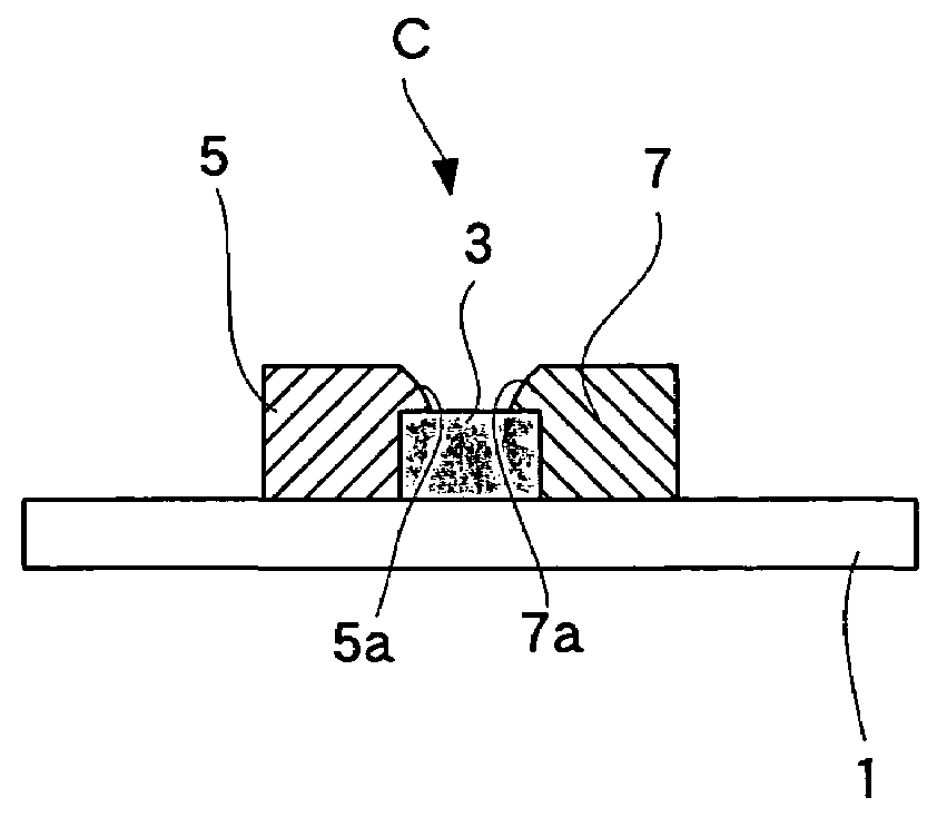
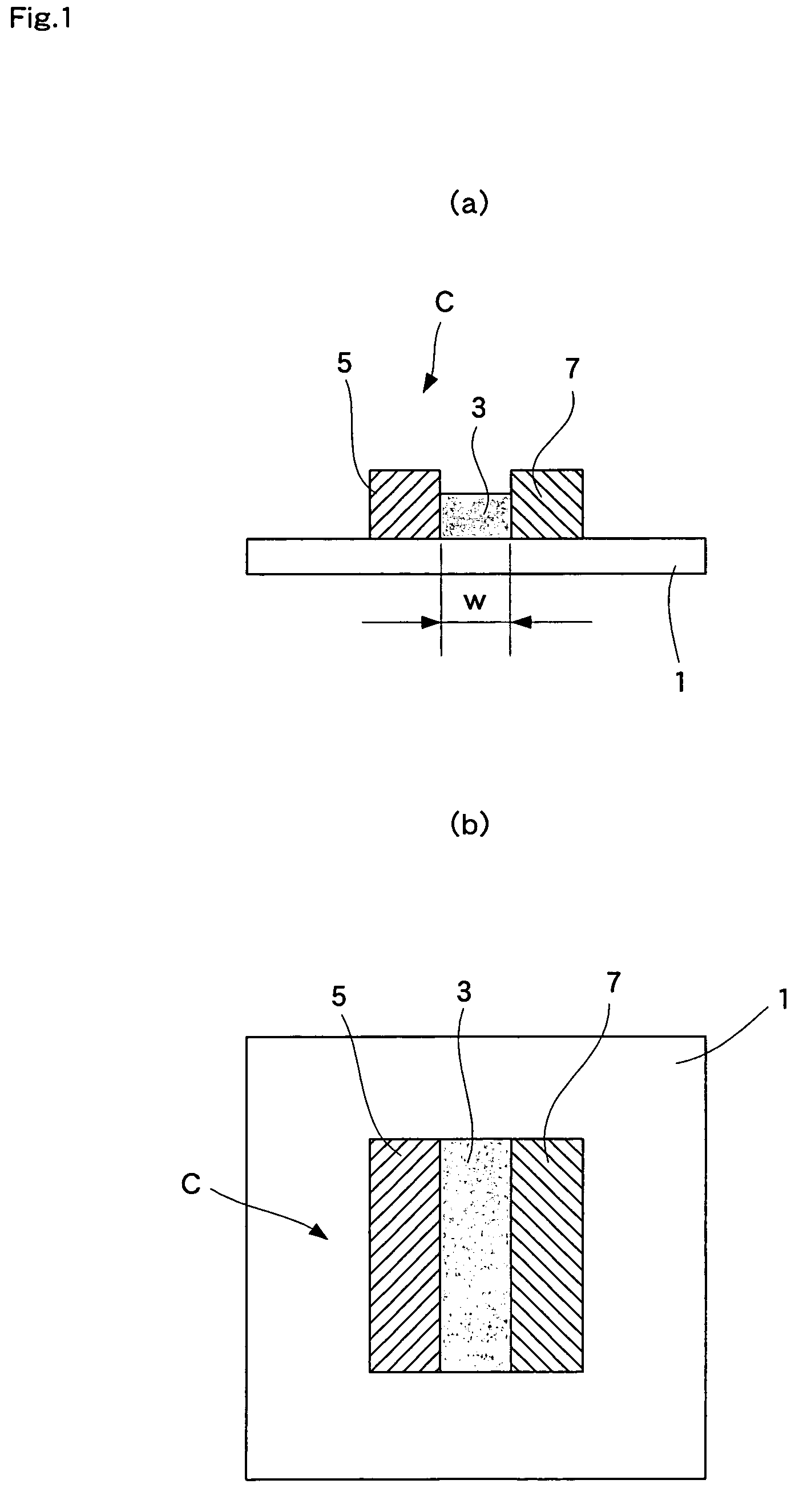
[0062]As shown in FIG. 6, this fuel cell comprises a single cell C having an electrolyte 3, a fuel electrode 5, and an air electrode 7, wherein the single cell C is supported by a substrate 1.

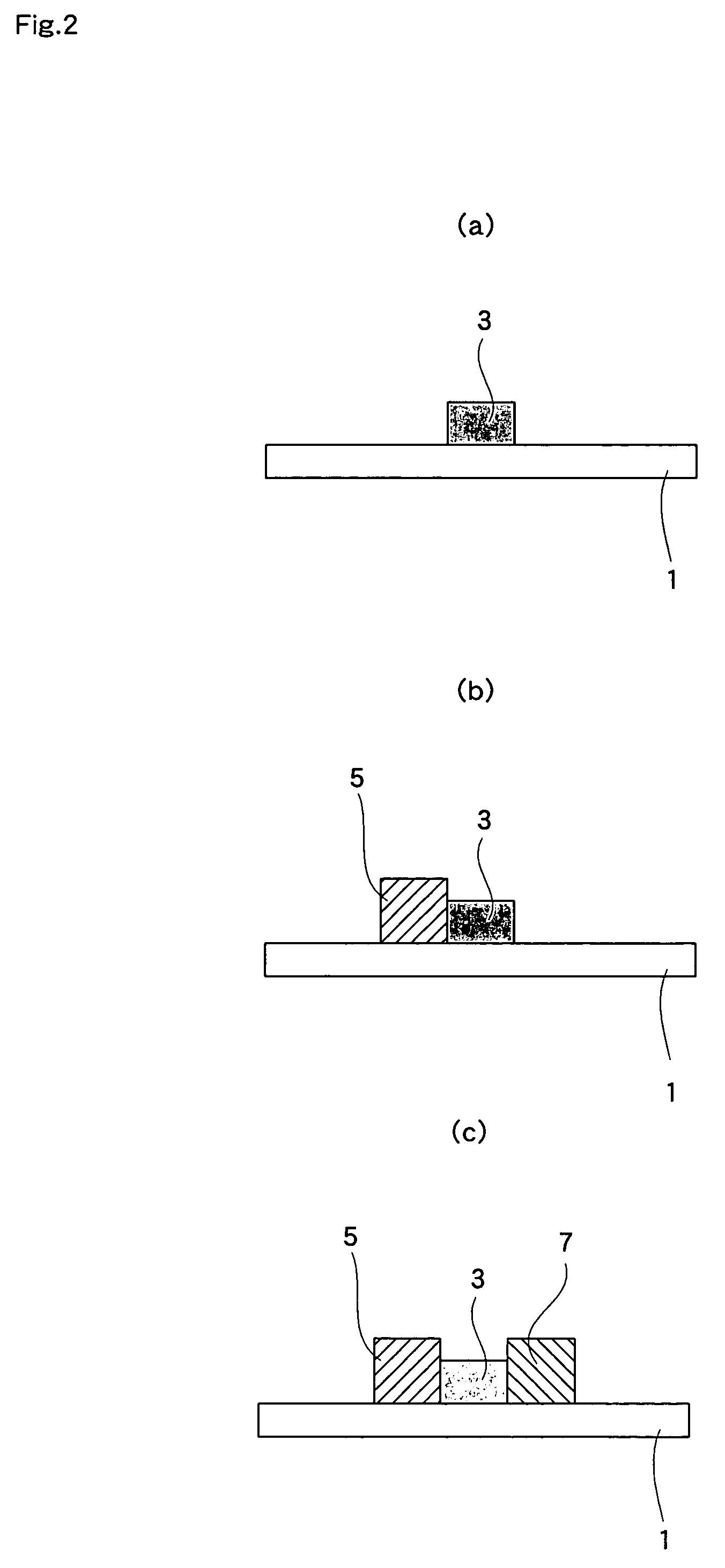
[0063]In the single cell C, the electrolyte 3 is rectangularly formed on top of the substrate 1 (one surface), and the air electrode 7 having essentially the same shape as the electrolyte 3 is formed thereon. The fuel electrode 5 is formed on the substrate 1 adjacent to the electrolyte 3. The fuel electrode 5 is in contact with the side face of the electrolyte 3 and the thickness thereof is less than the electrolyte 3. In other words, the top surface of the fuel electrode 5 is lower than that of the electrolyte 3. Therefore, the fuel electrode 5 and ...

example 1

[0082]Hereunder, the present invention is explained in detail with reference to Examples. In Example 1, the way the fuel cell shown in FIG. 5 was manufactured is explained.

[0083]SDC[(Ce, Sm)O3] powder (particle size; 0.01-10 μm, average particle size; 0.1 μm) was used as the material for the electrolyte 3 and mixed with cellulose-based varnish to obtain an electrolyte paste. The viscosity of the electrolyte paste was set at 5×10⁵ mPa·s, which is suitable for screen printing. Furthermore, as the material for the fuel electrode 5, a mixture of NiO powder (particle size: 0.01-10 μm, average particle size: 1 μm) and SDC [(Ce, Sm)O3] powder (particle size: 0.01-10 μm, average particle size: 0.1 μm) in a weight ratio of 7:3 was prepared, and the material was then mixed with cellulose-based varnish, giving a fuel electrode paste. The viscosity of the fuel electrode paste was set at 5×10⁵ mPa·s, suitable for screen printing. SSC[(Sm, Sr)CoO3] powder (particle size: 0.1-10 μm, average partic...


PUM


Abstract

A fuel cell including at least one single cell C having an electrolyte 3, a fuel electrode 5, and an air electrode 7, wherein the single cell C is supported on a substrate 1 and the electrolyte 3 is disposed on a first surface of the substrate 1, with the fuel electrode 5 and the air electrode 7 disposed on the first surface of the substrate 1 so as to sandwich the electrolyte 3.

Description

BACKGROUND OF THE INVENTION[0001]1. Field of the Invention[0002]The present invention relates to a fuel cell, specifically, to a fuel cell that stably generates electricity mainly in a mixed gas of fuel gas and air.[0003]2. Description of the Related Art[0004]Planar type (stack-type), tubular type (tube-type) and other types of cell designs have been conventionally proposed for fuel cells.[0005]As disclosed in Japanese Unexamined Patent Publication No. 1993-3045, a planar type cell comprises a fuel electrode and an air electrode disposed on the front and back surfaces, respectively, of a flat electrolyte. The thus formed cells are used in a condition where a plurality of cells are laminated having a separator between adjacent cells. The separator completely separates the fuel gas supplied to each cell from the air, and a gas seal is provided between each cell and separator. However, in this planar type cell, because the gas seal is provided by applying pressure to the constituent co...

Claims


Application Information

Patent Timeline
IPC IPC(8): H01M8/10H01M8/24H01M8/12
CPCH01M8/1226H01M8/1286H01M4/9033H01M8/124Y02E60/521Y02E60/525Y02P70/50Y02E60/50
Inventor YOSHIKATA, KUNIAKISAKAMOTO, HIROTOSHIMIKAMI, KOICHI
Owner DAI NIPPON PRINTING CO LTD
Why Eureka
Try Eureka