
Layered catalyst composite

Active Publication Date: 2009-04-14
BASF CATALYSTS LLC
View PDF16 Cites 111 Cited by
  • Summary
  • Abstract
  • Description
  • Claims
  • Application Information

AI Technical Summary

Problems solved by technology

Although many of these materials suffer from the disadvantage of having a considerably lower BET surface area than activated alumina, that disadvantage tends to be offset by a greater durability of the resulting catalyst.

Method used


Image

  • Layered catalyst composite
  • Layered catalyst composite

Examples


example 1

First Layer

[0053]The components present in the first layer were 10% baria stabilized gamma alumina, lanthanum oxide, strontium oxide, zirconium oxide, neodymium oxide, a composite of cerium and zirconium oxide with approximately 30% ceria content and palladium at the concentrations of 64%, 6.4%, 6.4%, 2.6%, 6.4%, 12.8% and 1.1%, respectively, based on the calcined weight of the catalyst. The palladium (30 g / ft3) in the form of palladium nitrate solutions were impregnated by planetary mixer (P-mixer) onto the stabilized alumina to form a wet powder while achieving incipient wetness. The other components such as promoters and stabilizers were introduced as their soluble salts using water as the slurrying vehicle. The aqueous slurry was formed by combining all above components and milled to a particle size of 90% less than 9 microns and coated onto the cordierite carrier. After coating, the carrier plus the first layer was calcined at a temperature of 550° C. for at least 2 hours.

Secon...


PUM

PropertyMeasurementUnit
specific surface areaaaaaaaaaaa
BET surface areaaaaaaaaaaa
temperaturesaaaaaaaaaa

Abstract

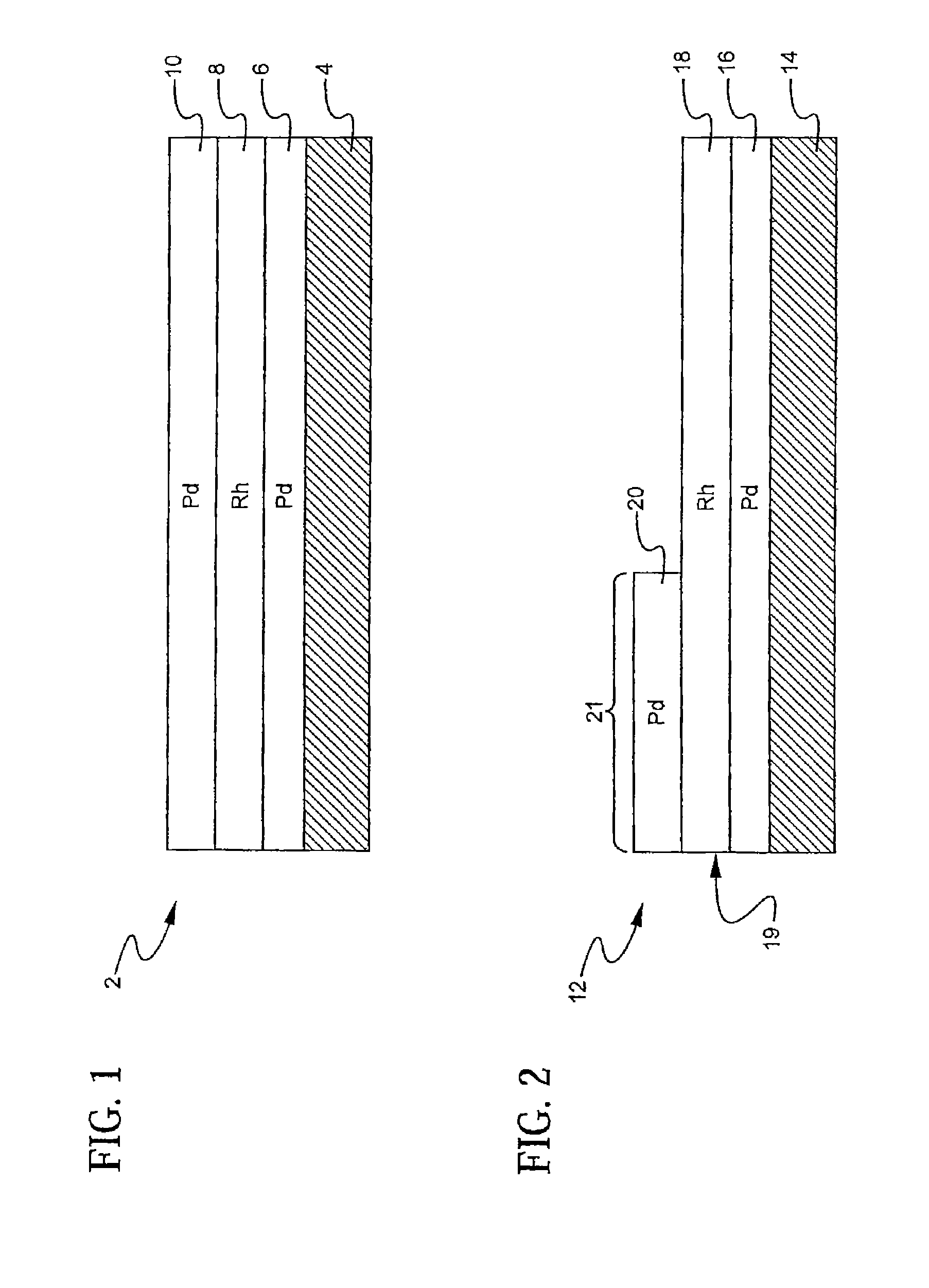
A layered, three-way conversion catalyst having the capability of simultaneously catalyzing the oxidation of hydrocarbons and carbon monoxide and the reduction of nitrogen oxides is disclosed. In one or more embodiments, the catalyst comprises three layers in conjunction with a carrier: a first layer deposited on the carrier and comprising palladium deposited on a refractory metal oxide and an oxygen storage component; a second layer deposited on the first layer and comprising rhodium deposited on a refractory metal oxide and an oxygen storage component; and a third layer deposited on the second layer and comprising palladium deposited on a refractory metal oxide.

Description

CROSS REFERENCE TO RELATED APPLICATION[0001]This application is a continuation-in-part of U.S. patent application Ser. No. 11 / 507,340, filed Aug. 21, 2006, now abandoned, which is hereby incorporated by reference in its entirety.TECHNICAL FIELD[0002]Embodiments present invention relate to a layered catalyst composite useful for the treatment of gases to reduce the level of contaminants contained therein. More specifically, embodiments of the present invention are concerned with catalysts of the type generally referred to as “three-way conversion” or “TWC” catalysts which have the capability of substantially simultaneously catalyzing the oxidation of hydrocarbons and carbon monoxide and the reduction of nitrogen oxides.BACKGROUND ART[0003]Three-way conversion catalysts have utility in a number of fields including the treatment of exhaust gas streams from internal combustion engines, such as automobile, truck and other gasoline-fueled engines. Emission standards for unburned hydrocarb...

Claims


Application Information

Patent Timeline
Patent Type & Authority Patents(United States)
IPC IPC(8): B01D53/56B01D53/62B01D53/72B01D53/86B01D53/94B01J23/44B01J23/46B01J35/00
CPCB01D53/945B01J23/40B01J23/464B01J23/58B01J23/63B01J37/0244B01D2255/102B01D2255/206B01D2255/407B01D2255/9025B01D2255/908B01J37/0234B01J37/0248Y02T10/22Y02T10/12
Inventor CHEN, SHAU-LIN F.RABINOWITZ, HAROLDSAKAKIBARA, JINLUO, TIAN
Owner BASF CATALYSTS LLC
Learn More