
Light guided assembly system

a technology of assembly system and light guide, which is applied in the direction of program control, total factory control, instruments, etc., can solve the problems of significant warranty cost to the manufacturer, add significant and undesirable cost and complexity to manufacturing operations, and improperly perform activities, etc., to achieve cost-effective and accurate effects

Active Publication Date: 2009-04-07
OPS SOLUTIONS
View PDF20 Cites 42 Cited by
  • Summary
  • Abstract
  • Description
  • Claims
  • Application Information

AI Technical Summary

Benefits of technology

"The present invention provides an operational guide system that uses visual indicators to guide an individual through a series of tasks. The system includes a controller, a sensor apparatus, a directional light device, and a display device. The controller receives input from the sensor apparatus and selectively provides command signals to the directional light device, which projects an indicating light to indicate the operation step location. The indicating light can be a number, word, shape, or video, and can be selectively configurable. The controller can also display information about the sequential actions on the display device. The system can be used in assembly, packaging, process preparation, and other applications, and can also be used for training individuals. The system can recognize the presence, type, and position of parts at a work station, and can also monitor cycle times and confirm the proper selection of parts by an operator. The technical effects of the invention include cost-effectiveness, accuracy, and flexibility in guiding individuals through assembly tasks."

Problems solved by technology

Numerous problems arise when such activities are improperly performed either from a workmanship standpoint and / or outside the standard time allowance.
In the case of workmanship, if the problem is not discovered prior to shipment of the work piece, a failure in the field may occur that can result in significant warranty costs to the manufacturer.
If the problem is discovered prior to shipment, the work piece may have to be scrapped or require re-work operations, both of which add significant and undesirable cost and complexity to the manufacturing operations.
In the case of failure to meet a standard time allowance, the entire assembly process may become unbalanced resulting in costly bottlenecks, excess inventory, and additional workmanship risk.
Automated machine vision systems, however, are expensive and are highly customized such that they are only able to handle a limited assortment of work pieces.
Such systems inherently involve human error such that a higher degree of nonconforming parts may go undetected.
Furthermore, when human inspection systems are constructed as separate “inspection stations” apart from the value added work operations, manufacturing costs are increased by allowing nonconforming work pieces to leave work stations.

Method used


Image

  • Light guided assembly system
  • Light guided assembly system
  • Light guided assembly system

Examples


Embodiment Construction

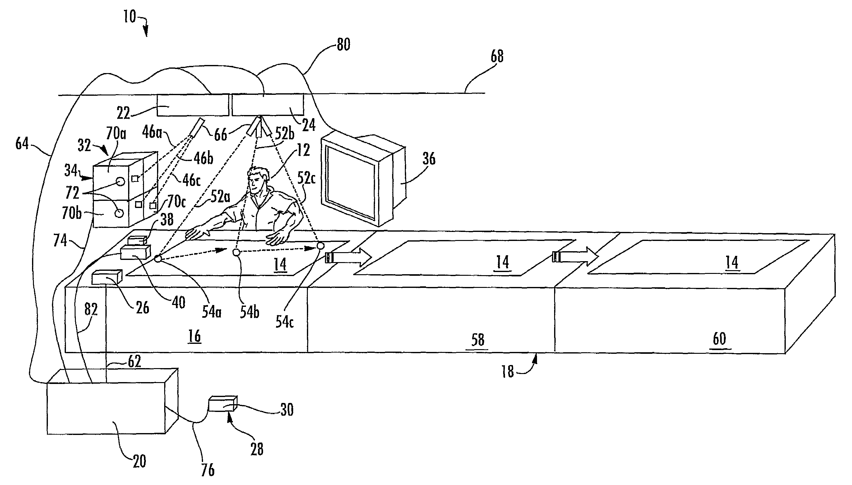
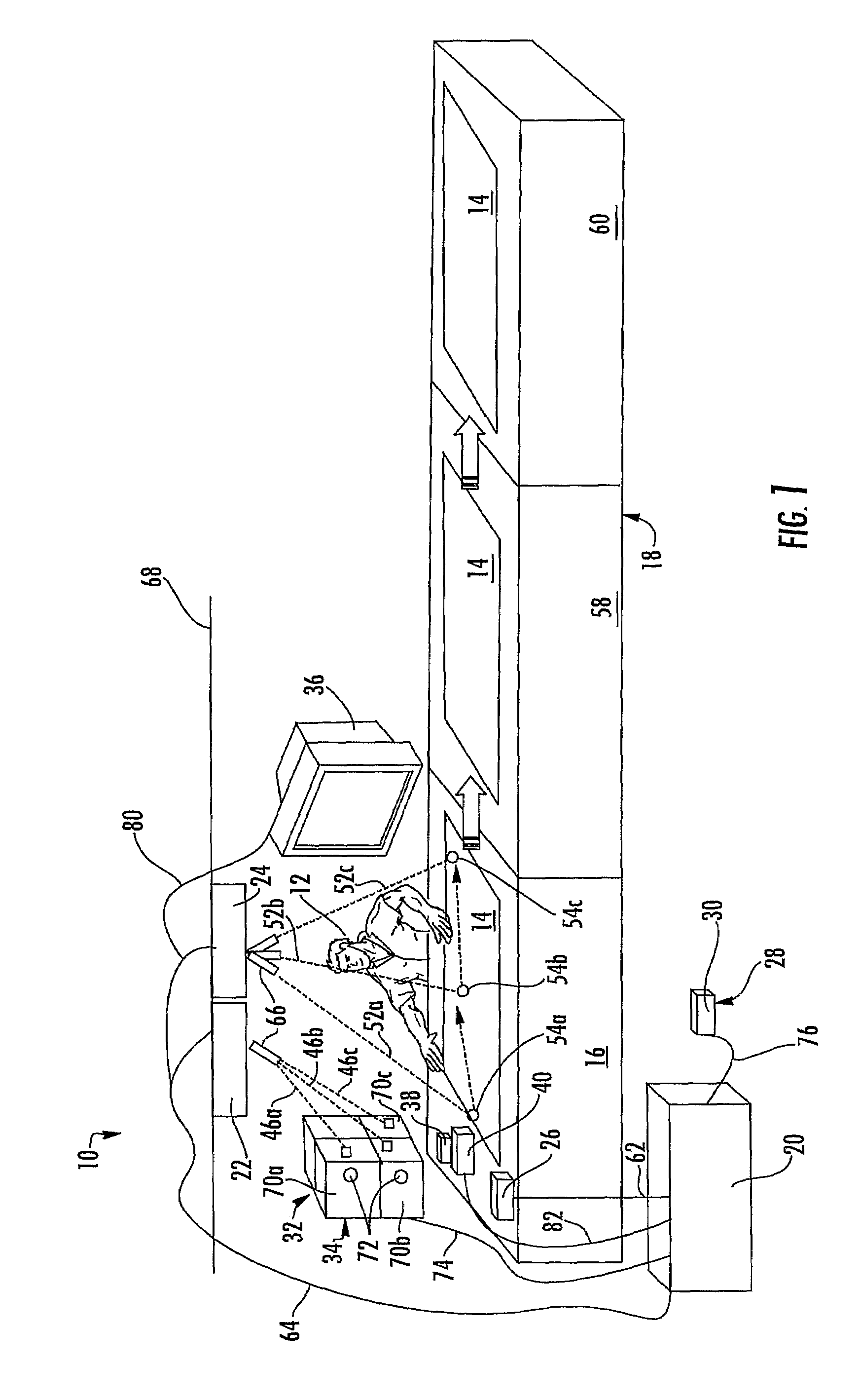
[0023]The present invention will now be described with reference to the accompanying figures, wherein the numbered elements in the following written description correspond to like-numbered elements in the figures. An operational guide system or assembly guide system 10 is illustrated in FIG. 1 in connection with the providing of visual indicators to an operator 12 performing one or more assembly actions on a work piece 14 at a work station 16 of an assembly line 18. The illustrated assembly guide system 10 includes a controller or a control module 20, two directional light devices 22, 24, a sensor apparatus 26, and a confirmation module or device or element 28, shown as a foot pedal 30. Assembly guide system 10 includes a component location 32, which is illustrated as a parts bin 34, a display device 36, and a tool 38 and tool holder 40.

[0024]Assembly guide system 10 is operable, in response to an operation information or characteristic or identification information associated with ...


PUM

PropertyMeasurementUnit
cycle timeaaaaaaaaaa
timeaaaaaaaaaa
flexibleaaaaaaaaaa

Abstract

An operational guide system (10) adapted to provide visual indicators to an individual to guide sequential actions includes at least one sensor apparatus (26), a controller (20), and at least one directional light device (22, 24). The sensor apparatus (26) is operable to detect operation information and generate an output indicative of the sensed operation information. The controller (20) receives at least a first input signal indicative of the operation information and selectively provides at least one command signal in response to the first input signal. The at least one directional light device (22, 24) being selectively operable to project and target at least one indicating light in response to the at least one command signal from the controller (20).

Description

CROSS REFERENCE TO RELATED APPLICATIONS[0001]The present application is a 371 national phase application of PCT Application No. PCT / US2006 / 39215, filed Oct. 6, 2006, which claims benefit of U.S. provisional application, Ser. No. 60 / 724,858, filed Oct. 7, 2005, and of U.S. provisional application Ser. No. 60 / 818,058, filed Jun. 30, 2006, which are all hereby incorporated herein by reference in their entireties.BACKGROUND OF THE INVENTION[0002]The present invention is directed to a system for guiding an individual in the performance of operational steps, and in particular a system that provides visual indicators to the individual.[0003]Numerous activities involve the performance of pre-designated operational steps to properly complete a particular task, with some such activities needing to be completed within a specified or standard time allowance. For example, in a manufacturing environment the selection and assembly of components to a work piece must be properly completed to satisfy...

Claims


Application Information

Patent Timeline
Patent Type & Authority Patents(United States)
IPC IPC(8): G06F19/00B23Q15/00G01M99/00
CPCG05B19/41805G05B2219/31027Y10T29/53039Y10T29/5303G05B2219/31048Y02P90/02
Inventor RYZNAR, PAULRYZNAR, JAMES
Owner OPS SOLUTIONS
Learn More