
Pupil reaction ascertaining device and fatigue recovery promoting device

a technology of pupillary reflex and ascertaining device, which is applied in the field of pupillary reflex checking apparatus and fatigue recovery promoting device, can solve the problems of difficult to relax, difficult to have the subject continue using the apparatus in the long term, and difficult to achieve the effect in practice, so as to facilitate the checking of the pupillary reflex, reduce the strain on the ciliary muscles, and reduce the effect of strain

Inactive Publication Date: 2009-03-17
WOC
View PDF3 Cites 5 Cited by
  • Summary
  • Abstract
  • Description
  • Claims
  • Application Information

AI Technical Summary

Benefits of technology

"The present invention relates to a pupillary reflex checking apparatus and a fatigue recovery facilitating apparatus. The pupillary reflex checking apparatus includes a reflecting unit and a stimulus applying unit, which can be used to check the subject's pupillary reflex. The apparatus can be used for a long period of time without causing eyestrain or fatigue. The technical effect of the invention is to provide a simple and cost-effective way to check the pupillary reflex and facilitate recovery from fatigue and eye strain caused by long periods of use with VDTs."

Problems solved by technology

Eyestrain and the like occur because modern working conditions, under which long periods are spent at VDTs or the like, cause the ciliary muscle and other muscles of the eye to be tensed continually, making them difficult to relax.
However, such an effect is difficult to achieve in practice because, if eyestrain is to be eased using the apparatus, the subject must for a certain period do nothing but stare at the optotype charge inside the apparatus.
Thus, it is difficult o have the subject continue using the apparatus in the long term.

Method used


Image

  • Pupil reaction ascertaining device and fatigue recovery promoting device
  • Pupil reaction ascertaining device and fatigue recovery promoting device
  • Pupil reaction ascertaining device and fatigue recovery promoting device

Examples


Embodiment Construction

[0038]The preferred embodiment of the present invention is described with reference to FIGS. 1 to 4. Hereafter, the characteristics and effects arising from the structure of the present invention are described using the fatigue recovery facilitating apparatus 1 as an example, but it is noted in advance that the present invention is not limited to what is described.

[0039](Structure of Fatigue Recovery Facilitating Apparatus 1)

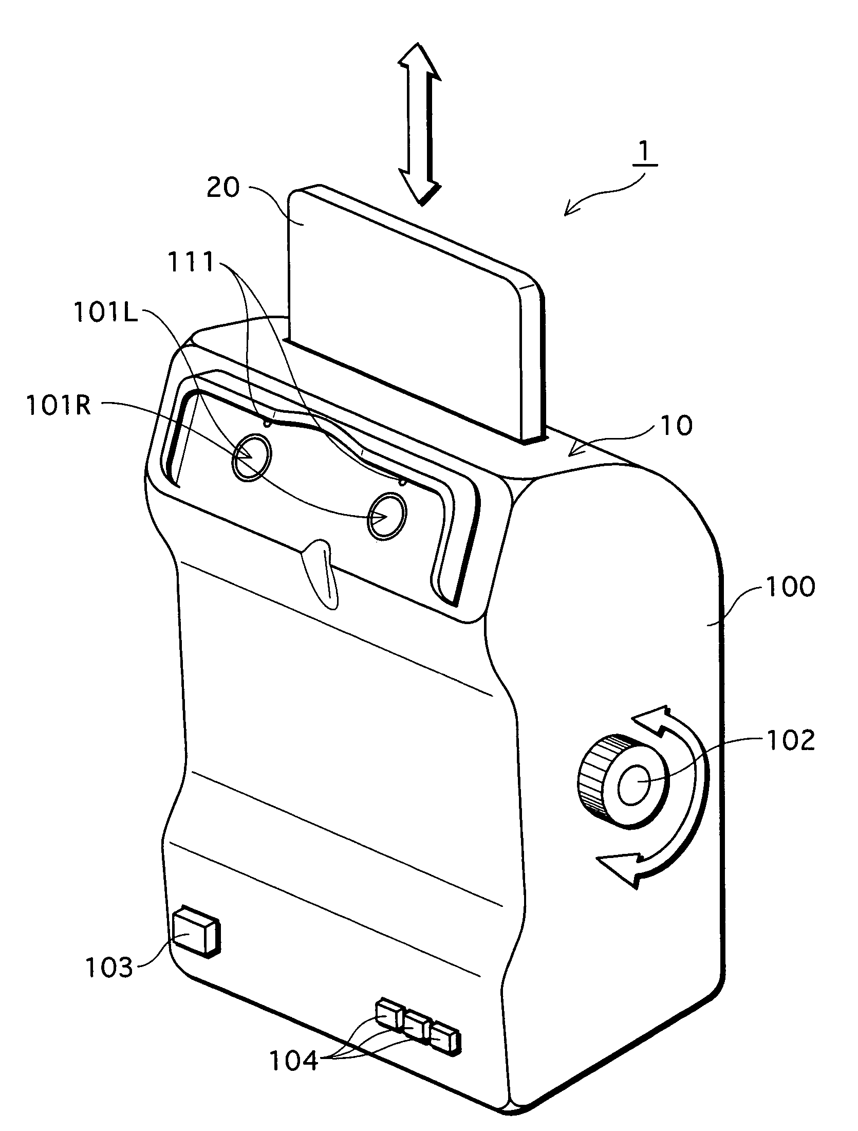
[0040]Firstly the overall structure of the fatigue recovery facilitating apparatus 1 is described using FIG. 1. FIG. 1 is a perspective view of the exterior of the fatigue recovery facilitating apparatus 1 of the embodiment of the present invention.

[0041]As shown in FIG. 1, the fatigue recovery facilitating apparatus 1 of the present embodiment is composed of a body 10 and a optotype chart 20 inserted for use therein. Of these, the body 10 includes a housing 100 which is substantially a rectangular parallelepiped (a parallelepiped with added irregularities), and...


PUM


Abstract

It is an object of the present invention to provide a pupillary reflex checking apparatus that enables a subject to check his own pupillary reflex and that keeps down cost and to provide a fatigue recovery facilitating apparatus that includes the pupillary reflex checking apparatus. The pupillary reflex apparatus of the present invention includes, as essential elements of its structure, a reflecting unit and a stimulus applying unit. Of these, the reflecting unit has a structure which includes an optical reflecting surface disposed in a plane that intersects with a visual axis of a subject such that an image of a pupil of a subject's eye is formed on the optical reflecting surface. Further, the stimulus applying unit applies a stimulus to induce the pupillary reflex in the subject. Specifically, it is possible to use a light source which gives a light stimulus to the subject's eye, such as an LED light source, an electric bulb, a strobe, or the like, as the stimulus applying unit.

Description

TECHNICAL FIELD[0001]The present invention relates to a pupillary reflex checking apparatus and a fatigue recovery facilitating apparatus which includes the pupillary reflex checking apparatus.Background Art[0002]In recent years, eye conditions, such as eye strain and “techno-stress” (Chronic Fatigue Syndrome), caused by working with VDTs (Visual Display Terminals) such as those used in PCs (Personal Computers) have become a significant object of public concern. Eyestrain and the like occur because modern working conditions, under which long periods are spent at VDTs or the like, cause the ciliary muscle and other muscles of the eye to be tensed continually, making them difficult to relax.[0003]Conventionally, methods such as telescopic methods, convex lens apparatus methods, eyedrop treatment methods, and the like have been used to facilitate recovery from conditions such as eye strain, but in recent years, apparatus which use “fogging” to relax the ciliary muscle and facilitate re...

Claims


Application Information

Patent Timeline
Patent Type & Authority Patents(United States)
IPC IPC(8): A61B3/10A61B3/00A61B3/032A61B3/11A61F9/00
CPCA61B3/0008A61B3/112A61B3/032
Inventor NAKAGAWA, AKIO
Owner WOC
Learn More