Liquid crystal display

a liquid crystal display and display technology, applied in non-linear optics, instruments, optics, etc., can solve the problems of the biggest defect of the tn type lcd, the fatal defect of the tft-lcd, and the narrow viewing angle, so as to suppress the drop in transmittance and improve the response characteristics

Inactive Publication Date: 2009-03-03
SHARP KK
View PDF38 Cites 10 Cited by
  • Summary
  • Abstract
  • Description
  • Claims
  • Application Information

AI Technical Summary

Benefits of technology

[0031]An object of the present invention is to provide a liquid crystal display in which a drop in transmittance is suppressed and response characteristics are improved.
[0032]Another object of the present invention is to provide a liquid crystal display in which a drop in response characteristics is suppressed and transmittance is improved.

Problems solved by technology

However, the TN type TFT-LCD has a fatal defect that a viewing angle is narrow.
This is the biggest defect of the TN type LCD.
However, a response time when a halftone is displayed from another halftone is rather inferior to the TN type TFT-LCD.
Besides, also with respect to the transmittance of light, although the conventional MVA system TFT-LCD is substantially twice as excellent as a wide viewing angle LCD of an IPS (In-plane Switching) system of a horizontal electric field system, it is inferior to the TN type TFT-LCD.
Thus, the pitch of the upper and lower projections cannot be made very short.
Accordingly, there arises a problem that if the formation density of the linear projections is made high in order to improve the response characteristics of the liquid crystal, the transmittance is lowered.
As stated above, the conventional MVA-LCD construction has a problem that the improvement of the response characteristics of the liquid crystal and the improvement of the transmittance have a trade-off relation.

Method used


Image

  • Liquid crystal display
  • Liquid crystal display
  • Liquid crystal display

Examples


first embodiment

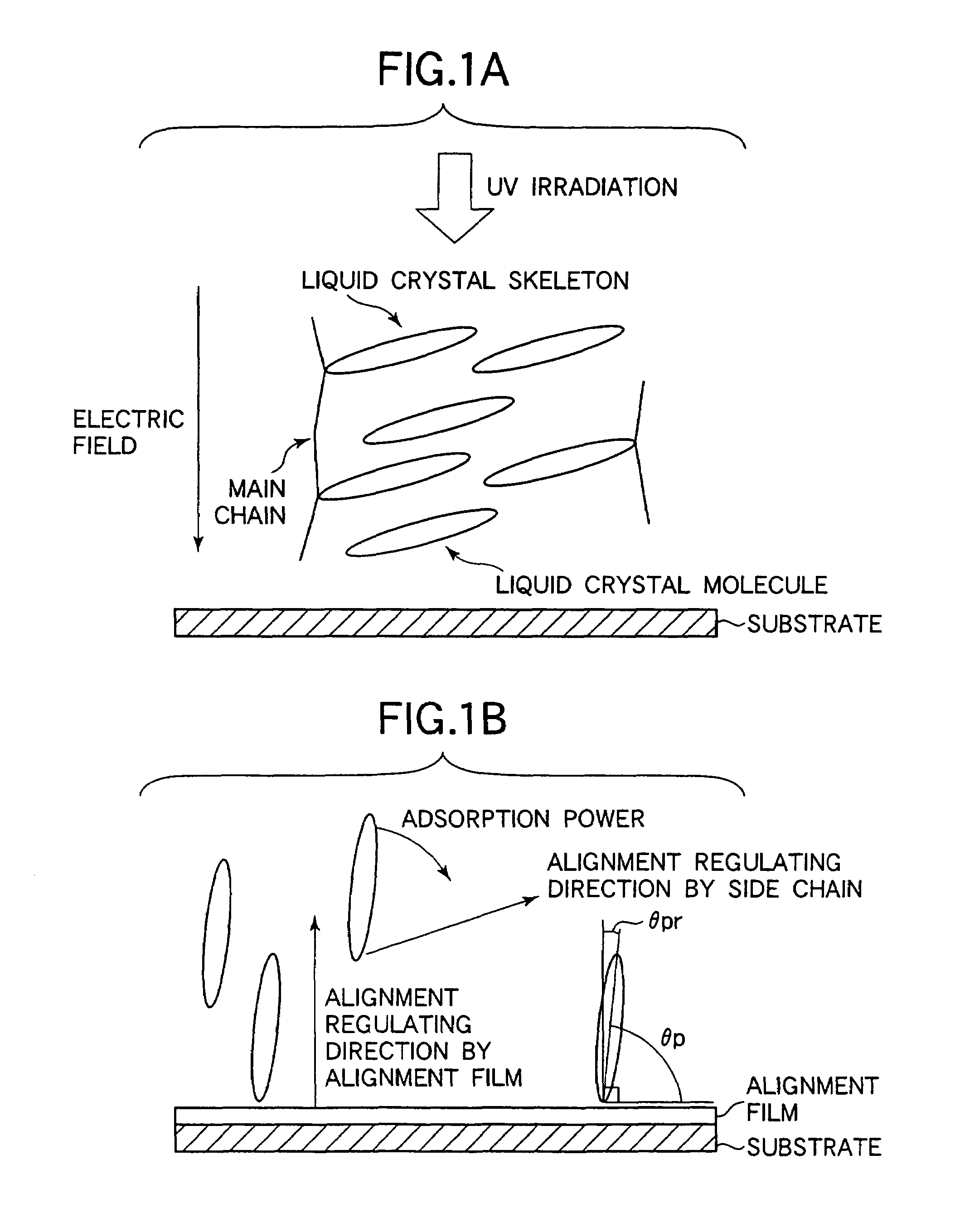
[0109]A liquid crystal display according to a first embodiment of the present invention will be described with reference to FIGS. 1A to 7. This embodiment is characterized in that in a liquid crystal display for regulating the alignment of all liquid crystal molecules at the time of voltage application by local alignment regulation, as typified by the above MVA system, a propagation process of a tilt of the liquid crystal molecule at the time of a response operation by voltage application is eliminated, and the whole display region is tilted at the same time. In addition, there is provided a liquid crystal display showing very high-speed response characteristics in all gradations by improving the response property itself of the liquid crystal molecules to an electric field.

[0110]In order to improve the response speed in the MVA system or the like, it is indispensable that a time required for tilt propagation of liquid crystal molecules is made zero and the whole surface of a display...

example 1-1

[0130]Liquid crystal monoacrylate monomer UCL-001-K1 of 2.5 wt % of Dainippon Ink Co., Ltd was added to liquid crystal material A having a negative dielectric anisotropy, and after being injected into an MVA cell, it was cured by ultraviolet rays while a voltage of 5.0 V was applied. Here, polyamic-acid material X was used as a vertical alignment film, banks (projections) each having a height of 1.5 μm and a width of 10 μm are alternately provided with resist LC-200 of Shipley Co., Ltd to make a space of 37.5 μm, and a cell gap was made 4.0 μm. A driving mode is normally-black.

[0131]FIG. 3 shows measurement results of response speed in this example. The horizontal axis indicates the transmittance (%) obtained when a predetermined voltage is applied from an applied voltage of 0 V, and the vertical axis indicates the response speed (ms; millisecond). A polygonal line α indicates a case where a photo-curing material is not added in the liquid crystal, and a polygonal line β indicates a...

example 1-2

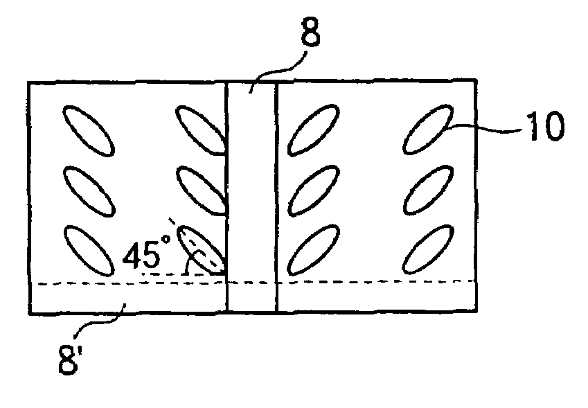
[0134]In the MVA cell of the example 1-1, when the alignment state at the time of voltage application of 5.0 V was observed, disturbance of alignment caused by singular points generated on the alignment regulating structural members as shown in FIG. 75 was observed in the space portion between the alignment regulating structural members. When the change of the alignment state with respect to the applied voltage at the time of photo-curing was examined, an excellent alignment was obtained till application of 3V, and the disturbance of the alignment became noticeable from the time of application of 3.5 V.

[0135]Next, the alignment film material was changed to a polyamic-acid material whose vertical alignment ability is much stronger than that of vertical alignment film material X. and when a similar experiment was carried out, an excellent alignment was obtained till application of 3.5 V.

[0136]FIG. 5 shows the relation between the tilt angle of liquid crystal molecules on the alignment...


PUM

PropertyMeasurementUnit
twist angleaaaaaaaaaa
azimuth angleaaaaaaaaaa
tilt angleaaaaaaaaaa

Abstract

A liquid crystal display including a pair of substrates arranged opposite to each other, electrodes respectively formed on opposite surfaces of the pair of substrates, and an alignment regulating structural member, formed on at least one of the pair of substrates, and which includes at least one of a linear projection arranged on the electrode and a slit portion formed by removing a part of an electrode material of the electrode. A liquid crystal layer is sealed between the substrates and has a negative dielectric anisotropy, in which alignment control is made such that when a voltage is applied to the electrodes, an alignment orientation of a liquid crystal domain in a region adjacent to the alignment regulating structural member is different from an extending direction of the alignment regulating structural member by approximately 45°, and at a time of no voltage application, a liquid crystal molecule of a region where the alignment regulating structural member does not exist is substantially vertically aligned, and a liquid crystal molecule on the alignment regulating structural member or on its opposite portion is un-vertically aligned.

Description

BACKGROUND OF THE INVENTION[0001]1. Field of the Invention[0002]The present invention relates to a liquid crystal display (LCD), and particularly to a liquid crystal display based on an MVA (Multi-domain Vertical Alignment) mode of multi-division alignment in which alignment states of liquid crystal molecules having a negative dielectric anisotropy are made different from each other.[0003]2. Description of the Related Art[0004]An LCD is regarded as the most promising substitute for a CRT among various flat panel displays. It is expected that the LCD has an extended market by being applied to not only a display monitor of a PC (Personal Computer), a word processor, or an OA equipment, but also a display portion of a consumer (household electric) appliance such as a large screen television or a portable small-sized television.[0005]A display operation mode of the LCD, which is most frequently used at present, is a normally-white mode using a TN (Twisted Nematic) liquid crystal. This L...

Claims


Application Information

Patent Timeline
Patent Type & Authority Patents(United States)
IPC IPC(8): G02F1/1337G02F1/1333G02F1/1343G02F1/137G02F1/139
CPCG02F1/133753G02F1/1393G02F1/1337G02F1/133707G02F1/13725
Inventor HANAOKA, KAZUTAKATANUMA, SEIJINAKANISHI, YOHEIUEDA, KAZUYAKATAOKA, SHINGOSASAKI, TAKAHIROTAKEDA, ARIHIROTSUDA, HIDEAKIMAYAMA, TAKATOSHIINOUE, YUICHISUGIURA, NORIO
Owner SHARP KK
Why Eureka
Try Eureka