
Resonant sensor assembly

a technology of resonant sensor and assembly, which is applied in the direction of piezoelectric/electrostrictive device details, piezoelectric/electrostrictive device details, device details, etc., can solve the problems of increasing the natural frequency of the resonator, reducing the production efficiency of the resonant, so as to achieve easy automation and quality factor, accurate manufacturing conditions, and the effect of high degree of quality

Inactive Publication Date: 2009-03-03
BRUNEL UNIVERSITY
View PDF8 Cites 1 Cited by
  • Summary
  • Abstract
  • Description
  • Claims
  • Application Information

AI Technical Summary

Benefits of technology

[0014]Screen printing of the piezoelectric material is a process which is readily automated and which can provide accurate manufacturing conditions and therefore which can provide products of reliable and repeatable quality.

Problems solved by technology

The applied stress effectively increases the stiffness of the resonator structure, which results in an increase in the resonator's natural frequency.
This technology is around 40 years old and the performance of strain gauges is generally limited by fatigue and creep.
The manufacture of resonators using such technology is relatively expensive and labour intensive and therefore difficult to automate.
Moreover, the technology has almost reached its limit in terms of performance levels.

Method used


Image

  • Resonant sensor assembly
  • Resonant sensor assembly
  • Resonant sensor assembly

Examples


Embodiment Construction

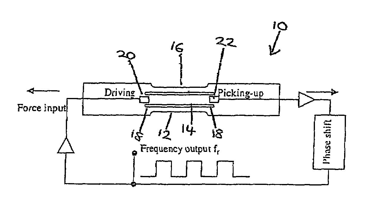
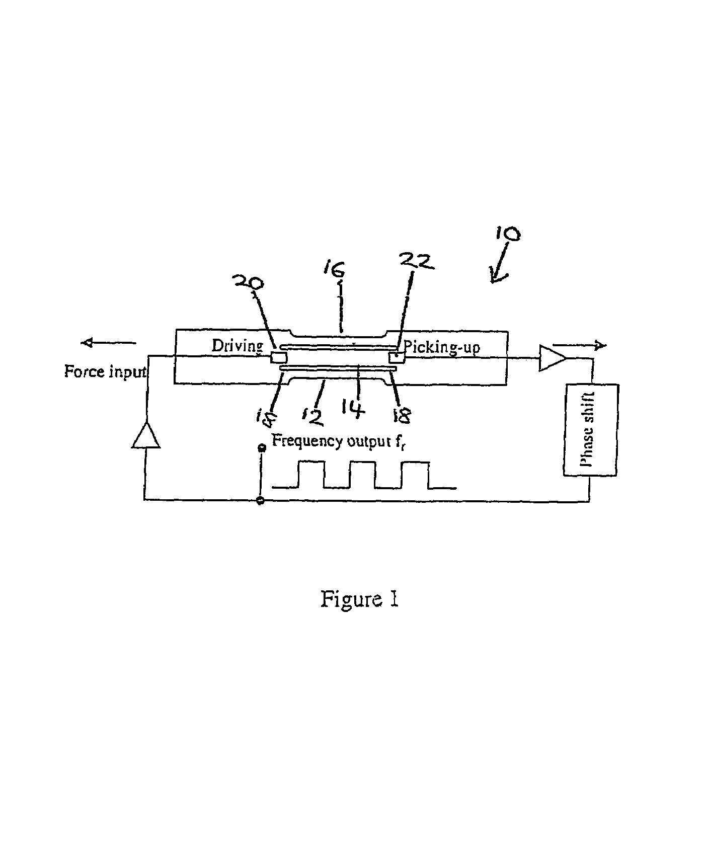
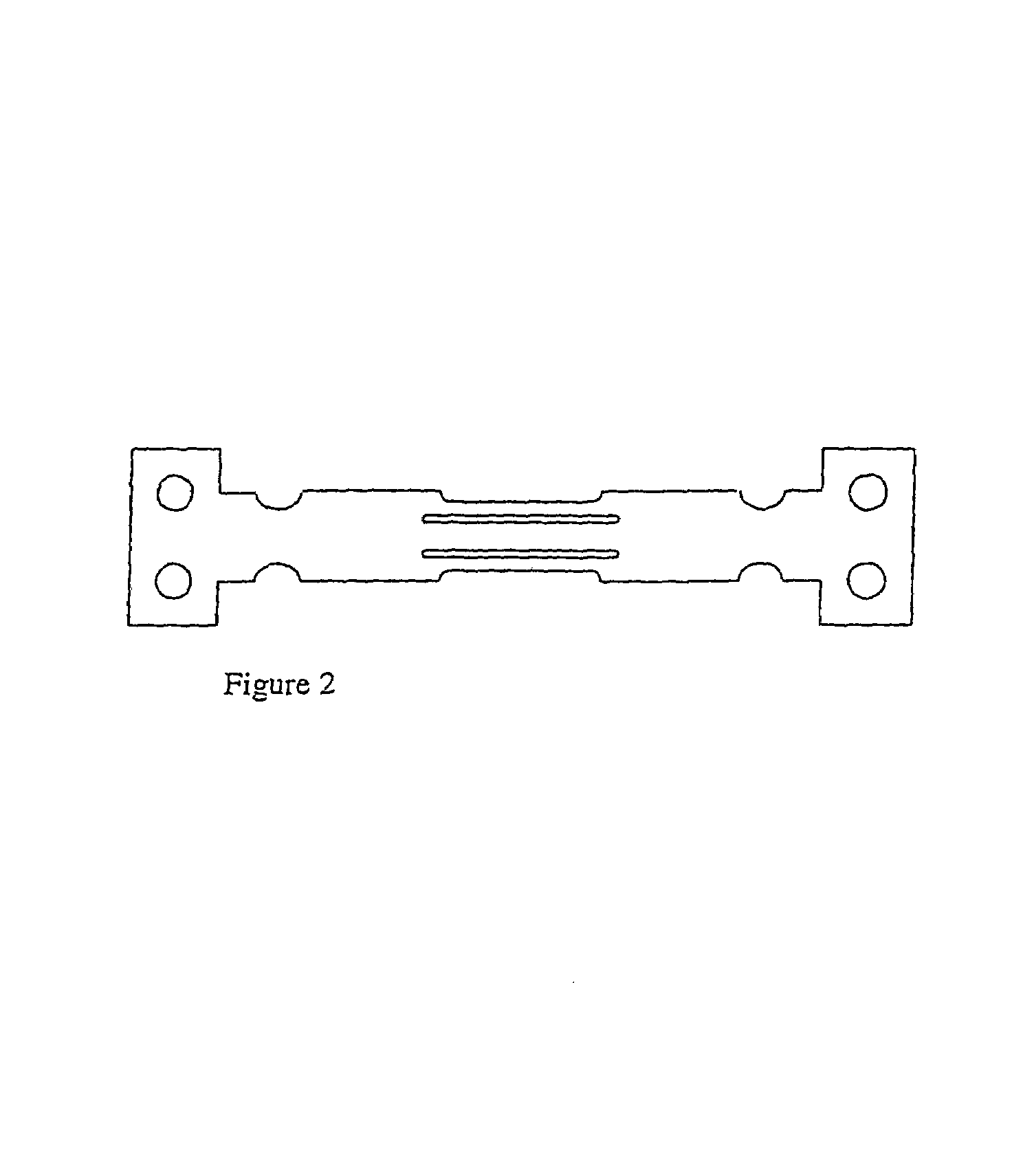
[0047]The preferred embodiments described herein provide a metallic, silicon or ceramic triple-beam resonator with thick-film piezoelectric elements to drive and detect the vibrations. In the case of a metallic resonator, the substrate of the preferred embodiment was fabricated by means of a double-sided photo chemical-etching technique and the thick-film piezoelectric elements were deposited by a standard screen printing process. An embodiment of resonator which was built and tested had a length of 15.5 mm, an overall width of 7 mm and had a favoured mode at 7.2 kHz with a Q-factor of 3100. The triple beam resonator could be described has having a tuning fork structure with thick-film piezoelectric drive and pickup elements.

[0048]Referring to FIG. 1, the embodiment of triple beam resonator shown is provided with printed thick-film piezoelectric drives and pickups. Thick piezoelectric films are batch screen printed onto the tines of the resonator at the correct positions to obtain t...


PUM


Abstract

A triple beam resonator (10) is provided with three beams or tines (12, 14, 16) aligned in parallel alongside each other and joined at a decoupling zone (18) at each end, which is in turn connected to the surrounding material. The central beam (14) is twice the width of the two outer beams (12, 16). The resonating element has a length of 15.5 mm, a thickness of 0.25 mm and beam widths of 2 mm and 1 mm. The distance between the beams is 0.5 mm. Finite element analysis predicts the modal behavior with stress distribution and eigenfrequencies of the resonator (10). Thick-film PZT elements (20, 22) were printed on separate regions at each end of the central beam (14), where maximum stresses exist as the resonator (10) operates in its favored mode of vibration. The PZT element (20) at one end drives the vibrations, while the PZT element (22) at the other end detects them. Positioning the PZT driving and sensing elements (20,22) on the regions of maximum stresses maximizes the degree of mechanical coupling between the active piezoelectric layer and the resonator for generation of both driving forces and sensing signals. Very high quality factors of 3100 and higher have been experienced. Furthermore, the resonator can be manufactures by batch production techniques while maintaining high reliability and reproducibility.

Description

FIELD OF THE INVENTION[0001]The present invention relates to a resonant sensor assembly.BACKGROUND OF THE INVENTION[0002]Resonant sensors have been used in a wide range of sensing applications, such as to measure load, pressure, torque and fluid flow characteristics. The key element of these sensors is the resonator, an oscillating structure, which is designed such that its resonance frequency is a function of the measurand.[0003]The most common sensing mechanism is for the resonator to be stressed as a force sensor. The applied stress effectively increases the stiffness of the resonator structure, which results in an increase in the resonator's natural frequency. The resonator provides a virtual digital frequency output, which is less susceptible to electrical noise and independent of the level and degradation of transmitted signals, offering good long-term stability. The frequency output is compatible with digital interfacing, requiring no analogue-to-digital conversion and theref...

Claims


Application Information

Patent Timeline
IPC IPC(8): H01L41/04H01L41/08G01L1/16G01L9/00
CPCG01L1/162G01L9/0022G01L1/16G01L9/00
Inventor JONES, EDWARD BARRYWHITE, NEIL M.TUDOR, JOHN M.BEEBY, STEPHEN P.
Owner BRUNEL UNIVERSITY
Learn More