
Three-dimensional input apparatus and image sensing control method

Inactive Publication Date: 2009-02-17
MINOLTA CO LTD
View PDF20 Cites 15 Cited by
  • Summary
  • Abstract
  • Description
  • Claims
  • Application Information

AI Technical Summary

Benefits of technology

[0024]An object of the present invention is to shorten the time required for three-dimensional data input at a predetermined angle of view without reducing the resolution and the distance range capable of three-dimensional data input.
[0025]Another object of the present invention is to produce an accurate three-dimensional image without necessity of processing for correcting the deviation between the timing of reading an intended pixel in an effective light-receiving area and the timing of shifting the effective light-receiving area by one line.
[0027]A further object of the present invention is to shorten the time required for three-dimensional data input and to lighten the burden of data processing by reducing the wasteful reading of an image sensing device.

Problems solved by technology

Narrowing the width of the belt-like zone for improving the speed, therefore, causes a problem of the reduced measurement range.
In other words, it is impossible to obtain concavo-convex information of the object.
In the case where the barycenter calculation is performed based on the data on a specific intended pixel in a plurality of effective light-receiving areas, therefore, the calculation result contains a considerable error and becomes unreliable.
For the calculation result to be reliable, the correction process may be necessary for reducing the deviation of timing, such process is very complicated.
Conversely, a low reflectance poses the problem of an inferior S / N ratio due to an excessively low output of the image sensing device.
In the case of an inferior S / N ratio as described above or in the case where the output of the image sensing device is saturated, an accurate barycenter calculation is difficult.
The accumulation time thus set, however, is shared by all the pixels of the image sensing device, and therefore the problem described above still remains unsolved in the case where the reflectance of the object is partially low or high.
In the case where an object is excessively small as compared with the visual field as mentioned above, therefore, the problem is that the unrequired data represents a large proportion of the data obtained by sampling, i.e. the data read operation from the image sensing device and subsequent data processing are very inefficient.

Method used


Image

  • Three-dimensional input apparatus and image sensing control method
  • Three-dimensional input apparatus and image sensing control method
  • Three-dimensional input apparatus and image sensing control method

Examples


first embodiment

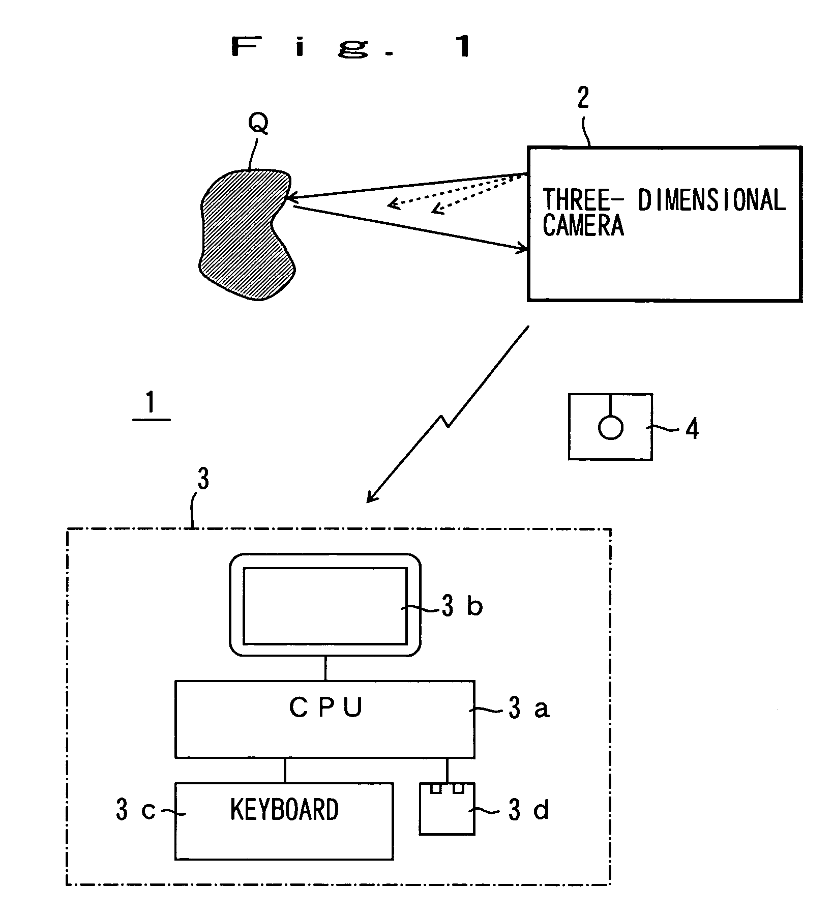
[0078]FIG. 1 is a diagram showing a configuration of a measuring system 1 according to this invention.

[0079]The measuring system 1 comprises a three-dimensional camera 2 for conducting three-dimensional measurement by the slit light projection method, and a host 3 for processing output data of the three-dimensional camera 2.

[0080]The three-dimensional camera 2 outputs a two-dimensional image indicating color information of an object Q and the data required for calibration as well as the measurement data specifying the three-dimensional position of a plurality of sampling points on the object Q. The calculation processing for determining the coordinates of the sampling points using triangulation are performed by the host 3.

[0081]The host 3 is a computer system including a CPU 3a, a display 3b, a keyboard 3c and a mouse 3d. The CPU 3a has built therein software for processing the measurement data.

[0082]Data can be transmitted and received between the host 3 and the three-dimensional c...

second embodiment

[0183]The basic configuration of the second embodiment is the same as that of the first embodiment. Specifically, FIGS. 1 to 5B, 7A to 10 and 17 to 19 and the description thereof applicable to the first embodiment are also applicable to the second embodiment. Only the portions of the second embodiment different from the first embodiment will be explained below.

[0184]The first embodiment refers to both the normal mode and the high-speed mode of the method of reading the frame by the image sensor 53. In the second embodiment, on the other, only the normal mode will be described.

[0185]FIG. 20 is a diagram showing the read range of the image sensor, and corresponds to FIG. 6 of the first embodiment. As shown in FIG. 20, in the normal mode, the thinned-out read operation is not performed unlike in the first embodiment, but all the data in the effective light-receiving area Ae are read out. Specifically, the skip read amount is set to zero in the skip read register 535 of FIG. 12, thereby...

third embodiment

[0231]The basic configuration according to the third embodiment is the same as that of the first and second embodiments. Specifically, FIGS. 1 to 5B, FIGS. 7A to 10 and FIGS. 17 to 19 for the first embodiment and FIG. 20 for the second embodiment and the description thereof are applicable also to the third embodiment. In the description that follows, therefore, the portions not included in the first and second embodiments will be explained.

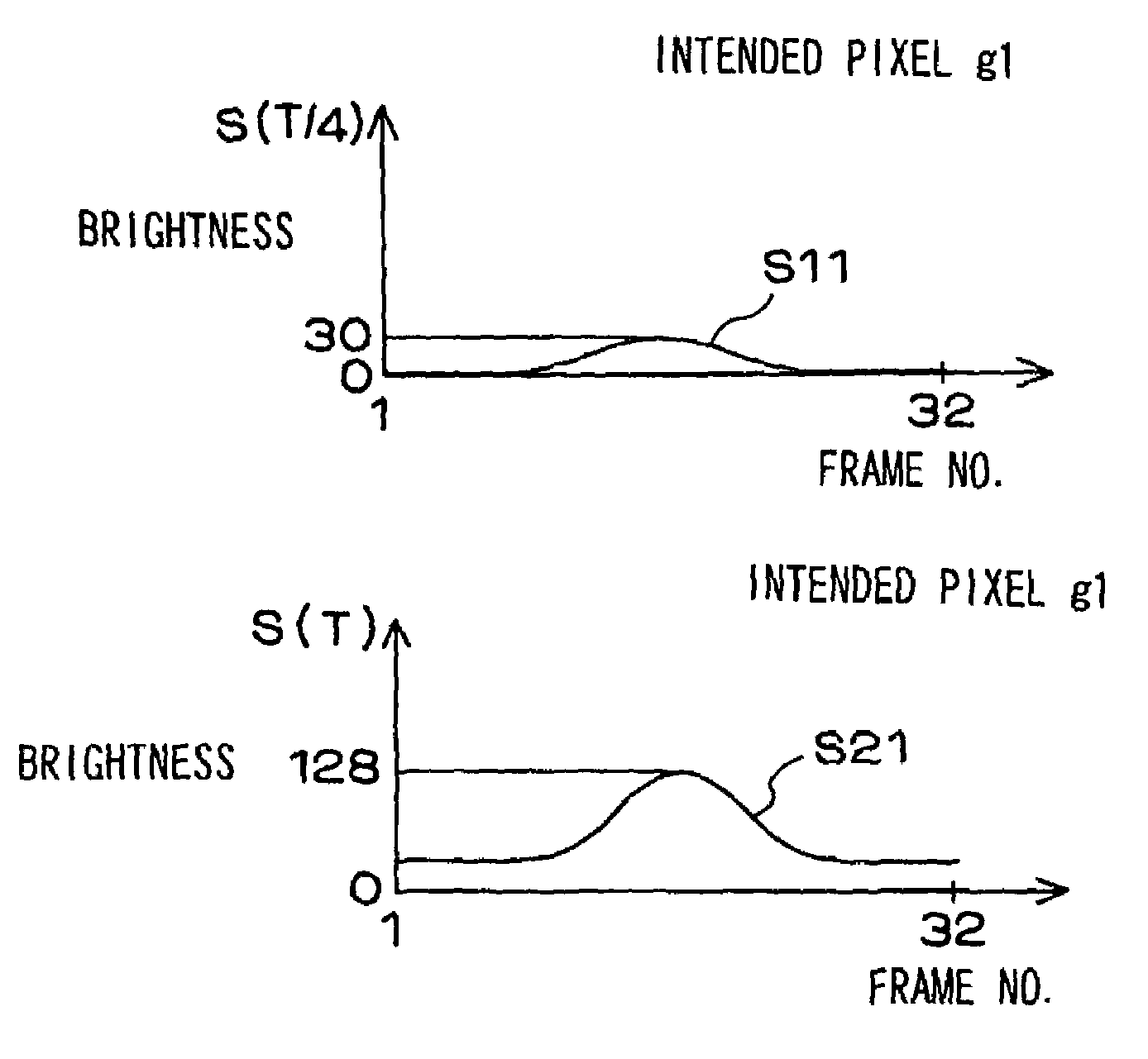
[0232]In the third embodiment, the image sensing information from the image sensor 53 is stored in a memory 63 through a select circuit 75 in synchronism with the clock from a driver 55. The image sensor 53 is controlled by a control signal in such a manner that the light-receiving data are read destructively. As a result, the light-receiving data S (T / n) having the charge accumulation time T / n and the light-receiving data S (T) having the charge accumulation time T, that is, n times larger than T / n are produced. An explanation will be given of a ...


PUM


Abstract

A three-dimensional input apparatus for generating data specifying the shape of an object by receiving the light from the object is disclosed. The detection light is irradiated toward the object by a projector so as to scan a virtual surface. An image sensing device detects the light reflected from the object. A controller thins out data and outputs it to the image sensing device in a direction corresponding to the main scanning direction of the virtual surface of the image sensing device. The controller also controls the image sensing device such that the light-receiving signal is repeatedly read on a line along the direction of movement of the received detection light in an effective area constituting a part of the image sensing surface thereby to read the light-receiving signal in the effective area.

Description

[0001]This application is based on Japanese Patent Application No. 274636 / 1998 filed on Sep. 29, 1998, No. 274637 / 1998 filed on Sep. 29, 1998, No. 274639 / 1998 filed on Sep. 29, 1998, and No. 81055 / 1999 filed on Mar. 25, 1999, the contents of which are incorporated herein by reference.BACKGROUND OF THE INVENTION[0002]1. Field of the Invention[0003]The present invention relates to an apparatus for inputting and outputting three-dimensional data that determine the shape of an object by irradiating a detection light beam such as a slit light beam or a spot light beam toward the object so as to scan the object and image sensing control method.[0004]2. Description of the Prior Art[0005]Conventionally, a three-dimensional measuring apparatus (an apparatus for inputting three-dimensional data), which is a non-contact type and enables rapid measurement compared with a contact type, is used for data input into a CG system or a CAD system, physical measurement, visual sense of a robot or other...

Claims


Application Information

Patent Timeline
IPC IPC(8): H04N3/14H04N5/335H04N5/353H04N5/369H04N13/00
CPCA61B1/00A61B5/0059G01B11/00G01S7/00G01S7/4861G01S17/89G02B26/10H04N3/1562H04N5/23245H04N5/3415H04N5/343H04N5/3452H04N5/347H04N13/021H04N13/0235H04N13/0253H04N13/211H04N13/254H04N13/236H04N23/667H04N25/41H04N25/441H04N25/42H04N25/443H04N25/46
Inventor NORITA, TOSHIOSATO, KAZUCHIKAOKADA, HIROYUKIMIYAZAKI, MAKOTOKAMON, KOICHI
Owner MINOLTA CO LTD
Learn More