
Method and apparatus for making dunnage

Inactive Publication Date: 2009-02-17
EIBERT RALPH
View PDF20 Cites 23 Cited by
  • Summary
  • Abstract
  • Description
  • Claims
  • Application Information

AI Technical Summary

Benefits of technology

[0007]It is therefore an object of the invention to produce air pillows on site in a manner that doesn't require heating elements to directly contact the air pillows to weld shut the air pillows.
[0010]It is a further object of the invention to produce air pillows on site by a process that seals the air pillows at improved operating speeds.
[0013]Typically, a roll of bags will be provided which is segmented longitudinally, but a roll can also be provided which is segmented both longitudinally and laterally, to produce a roll with, for example, four bags across or eight bags across. The bags can be separated from the roll individually or can be separated in groups. This is advantageous, as the air pillows which are produced can be wrapped around an object to protect it.
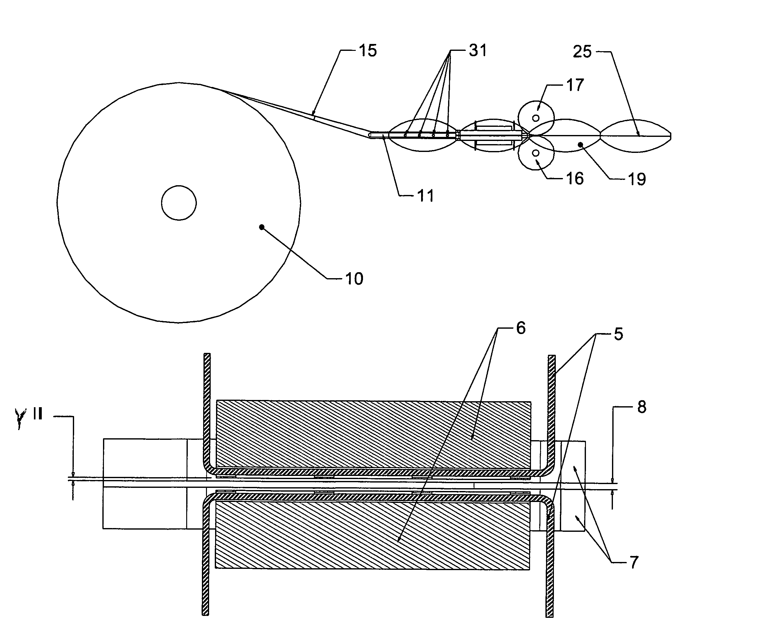
[0014]In accordance with the invention, the sealing of the open channel is accomplished using by passing the plastic over a ceramic element through which a heating element passes so that the layers of plastic melt and are welded to one another. By using a ceramic element with a heating element passing through it, the heating element never directly contacts the plastic and when the heating element is shut off, the heat dissipates quickly from the ceramic element. Further, the ceramic element is offset from the plane on which the plastic travels so that the ceramic element does not contact the plastic during operation. The heating element can be set to shut off as soon as the plastic stops moving, so that the ceramic elements dissipates its heat quickly, preventing static plastic from melting on and fouling the ceramic elements. As the ceramic element does not get fouled with melted plastic or plastic residue, the welding can occur at a higher rate than if the welding were done using heating elements that directly contacted the plastic. This technology will allow operating speeds that are almost 100-800% higher than existing machines.
[0015]Various types and thicknesses of material can be used to make the bags of the invention. The thickness of the material can be adjusted to provide extra strength or lighter weight, depending on which properties are desired.
[0017]In an additional embodiment of the invention, a metal knurled wheel is engaged with second wheel, possibly made of rubber, such that the plastic sheet material is pulled through the dunnage machine and the inflation and welding process. The welded seal can optionally be run directly between the knurled and second wheel to enable the knurled pattern to be embossed in the welded seal, thereby strengthening it.

Problems solved by technology

Air pillows are typically manufactured on site because it is inefficient to ship preformed air pillows since they take up considerably more volume than the sheet material.
However, these aforementioned processes and devices are disadvantageous in that because the heating elements must directly physically contact the plastic sheeting, they can become fouled from plastic that melts when the plastic sheeting stops moving through the devices.
When heating elements become fouled, the dunnage producing machines must be cleaned or the heating elements must be replaced, resulting in down time and lost production.
It is a further disadvantage that the aforementioned processes and devices are limited in their production speeds because of the need to allow the air pillow material to be physically melted between the heating elements to seal the air pillows, and because when the heating elements are fouled, speeds must be slower.
However the use of rubber wheels is disadvantageous because when the rubber wheels get dirty, slippage in the pillow material can occur.

Method used


Image

  • Method and apparatus for making dunnage
  • Method and apparatus for making dunnage
  • Method and apparatus for making dunnage

Examples


Embodiment Construction

[0026]While this invention is susceptible of embodiment in many different forms, there is shown in the drawings and will herein be described in detail specific embodiments, with the understanding that the present disclosure is to be considered as an example of the principles of the invention and not intended to limit the invention to the specific embodiments shown and described. While the following description describes a dunnage formation system, it should be recognized the embodiments disclosed can be utilized to manufacture pouches filled with any aqueous or gaseous material. In the description below, like reference numerals are used to describe the same, similar or corresponding parts in the several views of the drawing.

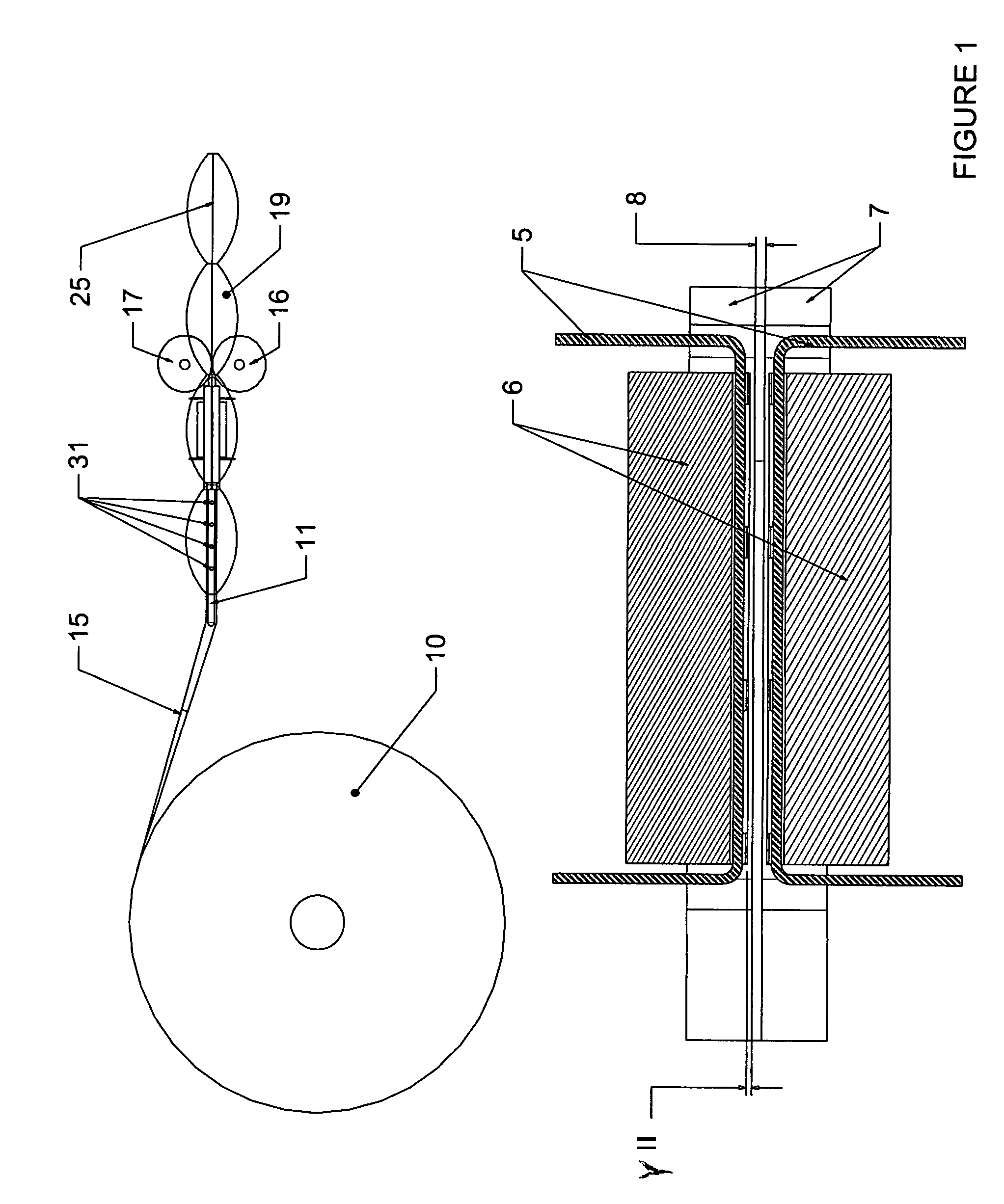
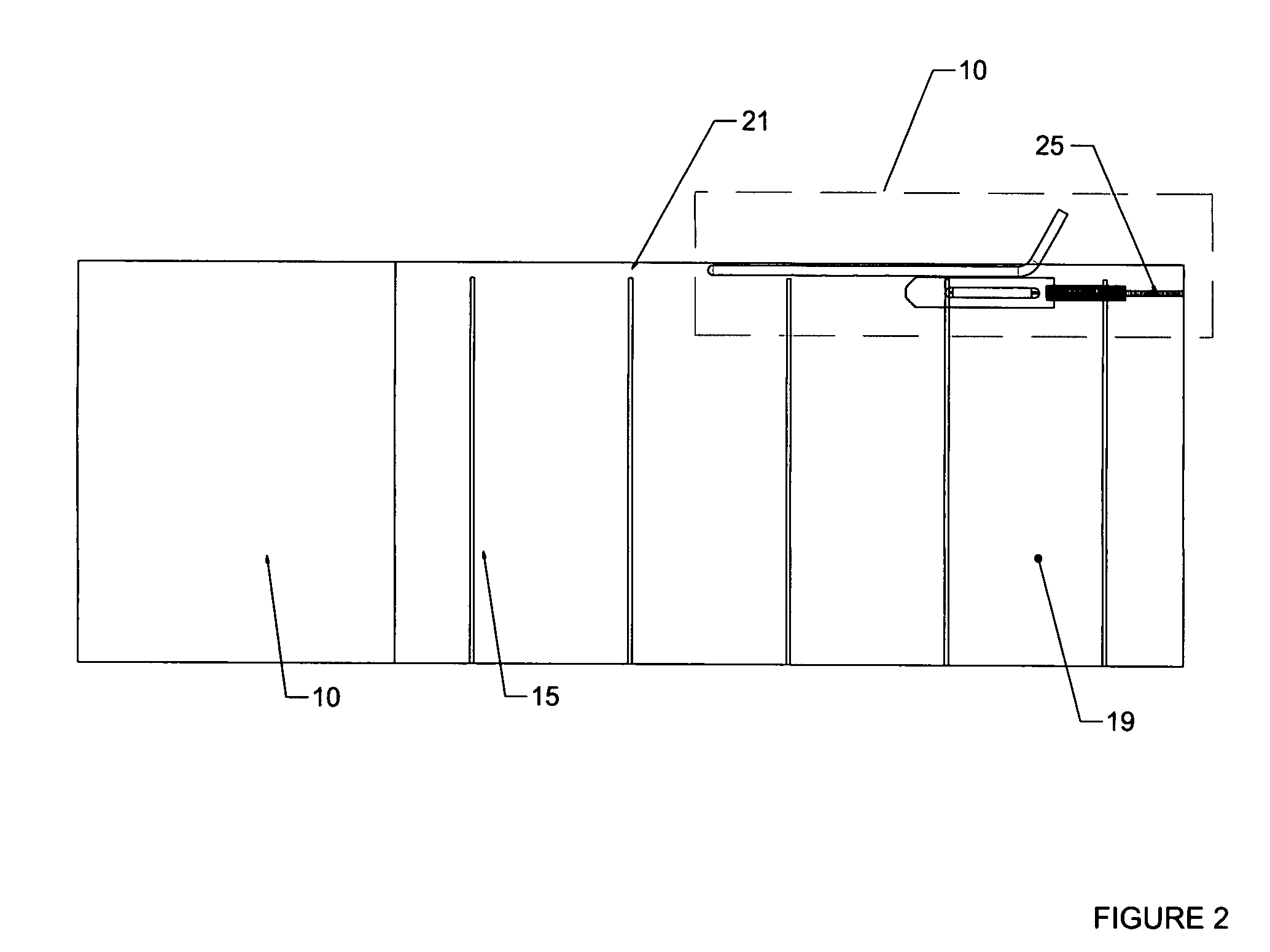
[0027]Referring now to the drawings and FIGS. 1 and 2 in particular, the process flow of a dunnage formation machine is shown. A web of plastic material 15 such as polypropylene is provided on a spool 10. The web is segmented longitudinally as shown in FIG. 2. Th...


PUM


Abstract

An apparatus for manufacturing dunnage including a plurality of rollers for pulling a web of material through the machine, a nozzle with at least one port through which gas or liquid flows, a plurality of ceramic elements in opposing positions such that the web of material can pass between the plurality of ceramic elements. A heating element is routed through each of the plurality of ceramic elements such that heat will radiate through openings in the top surfaces of the ceramic elements that will melt the portion of the material that is passing between the opposing ceramic elements. The apparatus may be equipped to manufacture multiple pieces of dunnage simultaneously.

Description

FIELD OF INVENTION[0001]The invention relates to an improved process for producing dunnage, or “air pillows.”BACKGROUND OF THE INVENTION[0002]Various materials are used to insulate goods from shock during shipping. Solid materials such as polystyrene “peanuts,” cups and “worms,” pellets of foam rubber, plastics and expanded polyurethane foam are in common use as a shock protector. Air cushioning material, or “air pillows,” are generally preferred over the above types of dunnage because it is lighter in weight, can be supplied and dispensed in a controlled manner, and can be manufactured on site. Air Pillows are typically manufactured using rolls of sheet material, which is also easier to dispose of than the individual pieces of plastic dunnage after the product is removed.[0003]Air pillows are typically manufactured on site because it is inefficient to ship preformed air pillows since they take up considerably more volume than the sheet material. Various devices have been described ...

Claims


Application Information

Patent Timeline
IPC IPC(8): B65B9/02B65B31/06B31B50/64
CPCB29C65/1467B29C66/1122B29C66/439B29C66/80B29C66/8167B29C66/87441B29C66/92611B31D5/0073B29C65/1445B29C66/43B29C66/8432B29C66/7352B29K2023/12B29K2909/02B29K2909/04B29L2022/02B29L2031/7138B31D2205/0011B32B2553/023B29C65/00Y10S493/967B29C66/836B29C66/73921B29C66/81871B29C66/8122B29C66/71B29C66/81821
Inventor EIBERT, RALPH
Owner EIBERT RALPH
Learn More