
Method and apparatus for enhanced alert notification

a technology of alert notification and enhanced technology, applied in the direction of dynamo-electric converter control, multiple dynamo-motor starters, liquid fuel engines, etc., can solve the problems of reducing system cost, affecting system performance, and affecting system performance, so as to reduce system cost

Active Publication Date: 2009-02-10
GULA CONSULTING LLC
View PDF2 Cites 17 Cited by
  • Summary
  • Abstract
  • Description
  • Claims
  • Application Information

AI Technical Summary

Benefits of technology

[0006]Accordingly, a need exists for improved alert notification in a computer system environment. A need also exists for alert notification with reduced system cost. Additionally, a need exists for alert notification which more clearly identifies which system or systems to which a fault pertains. Embodiments of the present invention provide novel solutions to these needs and others as described below.
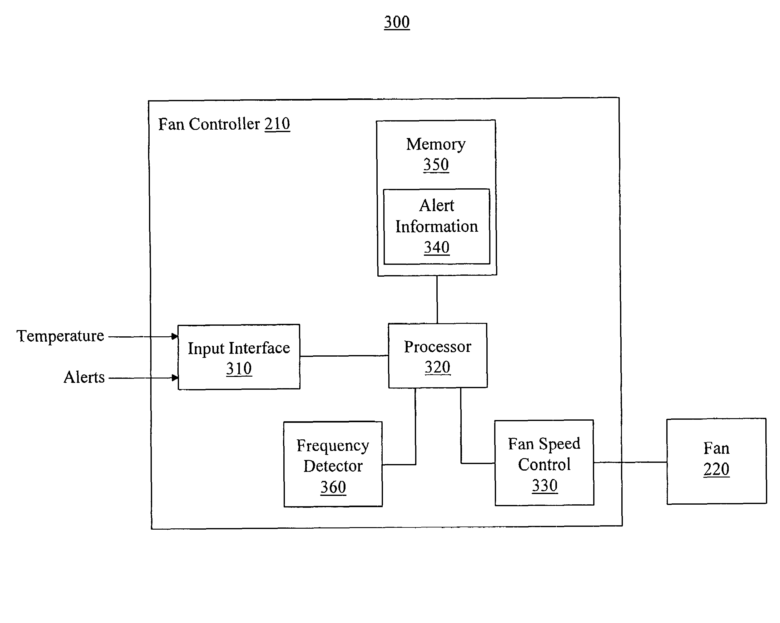
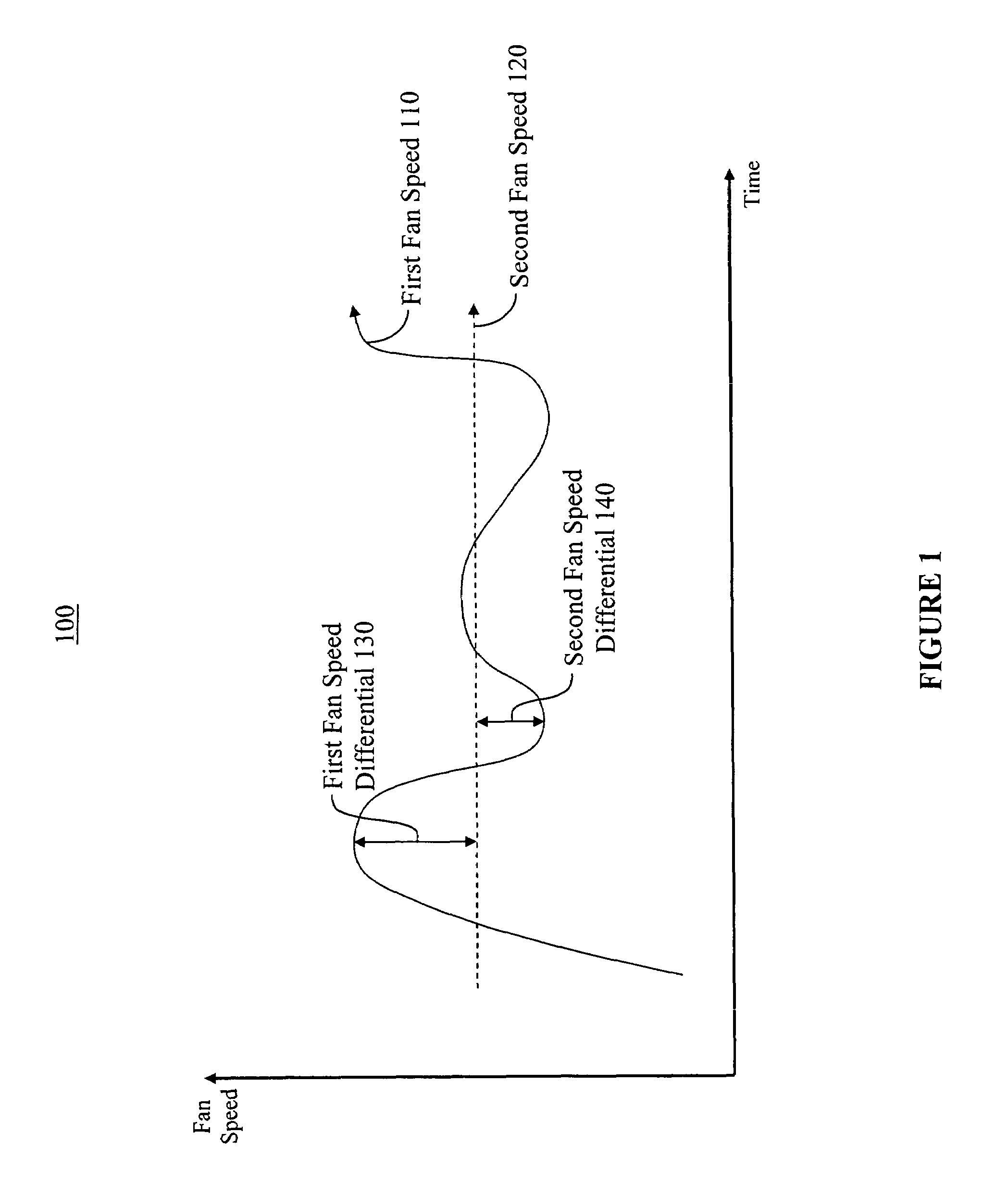
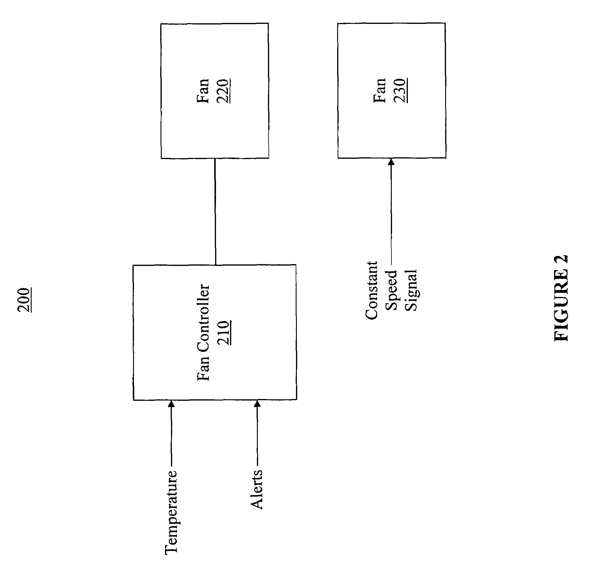
[0007]Embodiments of the present invention provide a system, fan controller and method for enhanced alert notification. More specifically, embodiments provide an effective mechanism for utilizing system fans to create alert tones or messages, where fan speed differentials may be adjusted to alter the frequency of the fan interference sounds. As such, existing hardware can be used to reduce cost by producing audible alerts which may be heard above ambient noise in a room with one or more electronic systems. Further, the frequency of the interference sounds may be altered to more clearly identify one or more systems to which a fault pertains.

Problems solved by technology

Since radiation and conduction are less-effective heat transfer methods in an enclosed system, convective cooling solutions are often used.
Regardless of the implementation, a spinning cooling fan will emit some noise.
Noise often results from the fan motor bearing, air moving past the fan blades and body of the fan, and the placement of the fan with respect to other objects (e.g., a vent in an electronic system chassis).
Additionally, a more pronounced noise may result from multiple fans spinning at different speeds, where the noise profiles from the fans intersect to produce a “beating” sound.
Given that the beating sound is often much louder and more annoying than the sound from an individual fan, conventional fan controllers attempt to spin proximately-located fans at precisely the same speed to reduce the beating sound.
Although the reduction of fan interference sounds is often important in a single electronic system with multiple fans, it becomes even more of an issue when multiple systems are placed in proximity to one another (e.g., in a computer server room).
Since each system is likely to have at least one fan, the placement of multiple systems in the same room can dramatically increase the number of fans which may interfere with one another and create beating sounds.
And moreover, given that the ambient air temperature of rooms containing multiple systems is often higher than rooms containing a single system, systems designed to be placed in the presence of other systems often contain more fans or larger fans that produce more noise.
As such, the beating sounds are often louder, more prevalent and more annoying than those associated with a single system.
Additionally, even if all fan speed differentials were eliminated, the ambient noise from the many fans is often very loud even without any beating.
As such, it is often hard to identify audible faults.
And even if a fault is identified, it is often hard to discern which system a given fault is associated with.
Similarly, given the large number of solid and blinking lights on multiple systems placed near one another, visual faults (e.g., a blinking light) are also hard to identify and distinguish.
Thus, given that most electronic systems are equipped with such audible and visual fault indicators, the price of the systems is increased while still providing poor fault indication.

Method used


Image

  • Method and apparatus for enhanced alert notification
  • Method and apparatus for enhanced alert notification
  • Method and apparatus for enhanced alert notification

Examples


Embodiment Construction

[0020]Reference will now be made in detail to embodiments of the present invention, examples of which are illustrated in the accompanying drawings. While the present invention will be discussed in conjunction with the following embodiments, it will be understood that they are not intended to limit the present invention to these embodiments alone. On the contrary, the present invention is intended to cover alternatives, modifications, and equivalents which may be included with the spirit and scope of the present invention as defined by the appended claims. Furthermore, in the following detailed description of the present invention, numerous specific details are set forth in order to provide a thorough understanding of the present invention. However, embodiments of the present invention may be practiced without these specific details. In other instances, well-known methods, procedures, components, and circuits have not been described in detail so as not to unnecessarily obscure aspect...


PUM


Abstract

A system, fan controller and method for enhanced alert notification. Embodiments provide an effective mechanism for utilizing system fans to create alert tones or messages, where fan speed differentials may be adjusted to alter the frequency of the fan interference sounds. As such, existing hardware can be used to reduce cost by producing audible alerts which may be heard above ambient noise in a room with one or more electronic systems. Further, the frequency of the interference sounds may be altered to more clearly identify one or more systems to which a fault pertains.

Description

RELATED APPLICATIONS[0001]The present application is related to and claims the benefit of U.S. Provisional Application No. 60 / 722,626, filed Sep. 29, 2005, entitled “FAN CONTROLLER WITH ALERT CAPABILITY,” naming Steven P. Larky and Darrin Vallis as the inventors, assigned to the assignee of the present invention. That application is incorporated herein by reference in its entirety and for all purposes.BACKGROUND OF THE INVENTION[0002]Many electronic systems require cooling to dissipate heat generated by electronic components. Since radiation and conduction are less-effective heat transfer methods in an enclosed system, convective cooling solutions are often used. As such, a common electronic system may have one or more fans to drive air over components, exhaust warm air from the system and draw cooler air into the system.[0003]Regardless of the implementation, a spinning cooling fan will emit some noise. Noise often results from the fan motor bearing, air moving past the fan blades ...

Claims


Application Information

Patent Timeline
Patent Type & Authority Patents(United States)
IPC IPC(8): H02P5/00
CPCF04D27/004F04D27/0292F04D29/582F04D29/005F04D27/008Y02B30/70
Inventor LARKY, STEVEN P.VALLIS, DARRIN
Owner GULA CONSULTING LLC
Learn More