
Motorcycle

a technology for motorcycles and cooling structures, applied in the field of motorcycles, can solve the problems of hot air and less cooling effect, and achieve the effect of avoiding an increase in the temperature of fuel

Inactive Publication Date: 2009-02-03
YAMAHA MOTOR CO LTD
View PDF13 Cites 22 Cited by
  • Summary
  • Abstract
  • Description
  • Claims
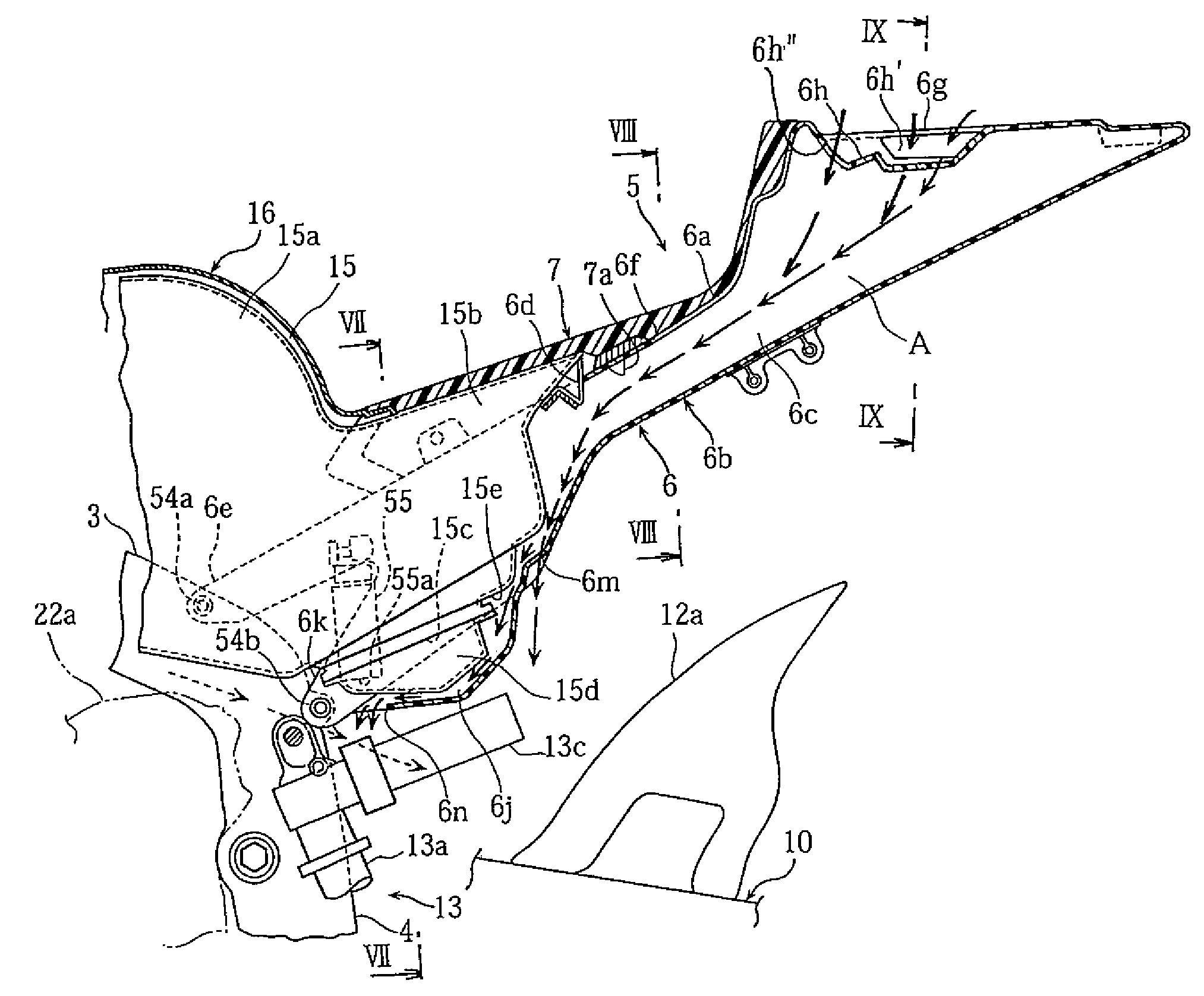
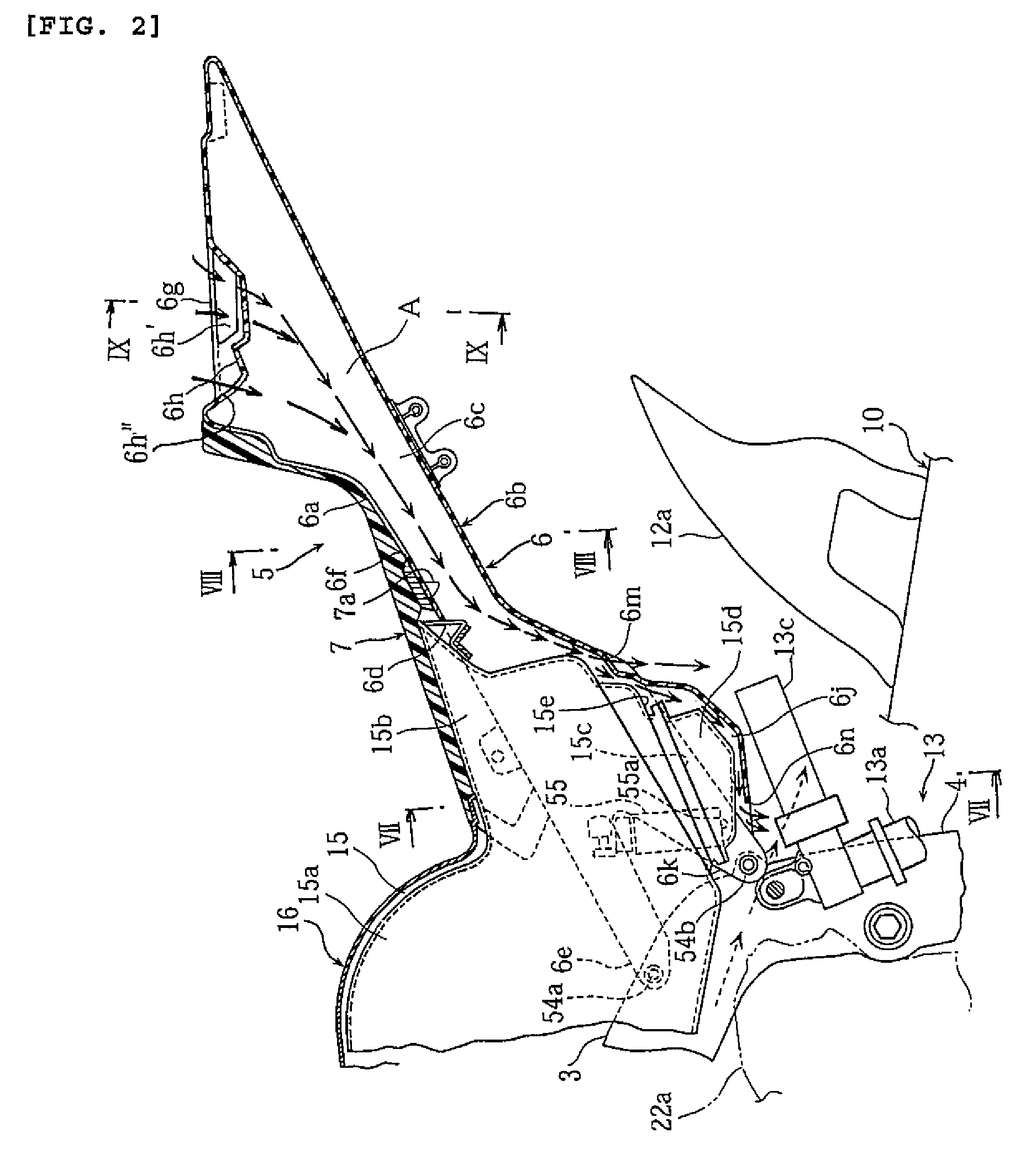
  • Application Information

AI Technical Summary

Benefits of technology

[0007]The present invention provides a motorcycle in which a bottom portion of a fuel tank is prevented from being heated by engine heat to thereby avoid an increase in the temperature of the fuel.
[0010]A positive pressure area develops on a surface of the seat frame behind the seat cushion under the influence of a running wind, and a negative pressure area develops between the bottom portion of the fuel tank and the engine. An air introduction opening is formed in the part of the seat frame behind the seat cushion, and an air passage is formed extending from the air introduction opening toward the bottom wall of the fuel tank to guide air from the air introduction opening through the air passage toward the bottom wall of the fuel tank, to thereby cool the bottom portion of the fuel tank. The air is ambient air under no influence of engine heat or the like, which effects reliable cooling of the bottom portion of the fuel tank. While it is possible to use the air flowing between the engine and the bottom portion of the fuel tank to cool the. fuel tank, such air might be hot due to engine heat and provides less cooling effect.

Problems solved by technology

While it is possible to use the air flowing between the engine and the bottom portion of the fuel tank to cool the. fuel tank, such air might be hot due to engine heat and provides less cooling effect.

Method used


Image

  • Motorcycle
  • Motorcycle
  • Motorcycle

Examples


Embodiment Construction

[0021]An embodiment of the present invention is now described with reference to the accompanying drawings.

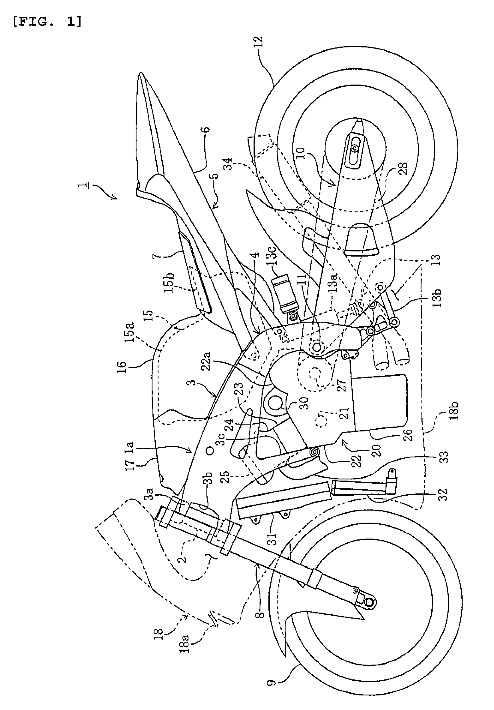
[0022]FIGS. 1-7 illustrate a motorcycle according to an embodiment of the present invention. In this description, the terms “front”, “rear”, “left” and “right” mean the front, rear, left and right directions from the perspective of a rider on the seat.

[0023]In the figures, reference numeral 1 denotes a motorcycle. A front wheel 9 and a rear wheel 12 are disposed forward and rearward of a body frame 1a. An engine 20 is suspended from and supported by a lower part of the body frame 1a. A cowling 18 surrounds the front, left and right sides of the engine 20.

[0024]The body frame 1a includes a head pipe 2; left and right tank rails 3, 3 extending from the head pipe 2 obliquely downward and rearward; and left and right rear arm brackets 4, 4 extending from the rear ends of the tank rails 3, 3 downward. A seat 5 is attached to the rear arm brackets 4, 4.

[0025]A front fork 8 is supporte...


PUM


Abstract

A bottom portion of a fuel tank of a motorcycle is prevented from being heated by engine heat to avoid an increase in fuel temperature. The fuel tank is behind and above the engine and a seat is behind the fuel tank. The seat includes a seat frame attached to the body frame and extending rearward, and a seat cushion mounted on the seat frame. The seat frame has an air introduction opening formed behind the seat cushion, and defines an air passage for guiding air introduced from the air introduction opening toward a bottom wall of the fuel tank.

Description

RELATED APPLICATIONS[0001]This application claims the benefit of priority under 35 USC 119 of Japanese patent application no. 2005-340817, filed on Nov. 25, 2005, which application is hereby incorporated by reference in its entirety.BACKGROUND OF THE INVENTION[0002]1. Field of the Invention[0003]The present invention relates to a motorcycle, and more specifically to a cooling structure that avoids an increase in temperature of a fuel tank mounted above the engine.[0004]2. Description of Related Art[0005]Motorcycles are generally constructed such that an engine is suspended from and supported by a lower central part of a body frame; a fuel tank is mounted above the engine; and a seat is disposed behind the fuel tank (see JP-A-2003-112678).[0006]When the engine and the fuel tank are mounted in this conventional positional relationship, a bottom portion of the fuel tank is heated by engine heat, resulting in an increase in the temperature of fuel in the fuel tank. Conventionally, to av...

Claims


Application Information

Patent Timeline
Patent Type & Authority Patents(United States)
IPC IPC(8): B60P3/22B62J35/00B62J99/00
CPCB62J1/12B62J17/00B62K11/04
Inventor TSUYA, KOJI
Owner YAMAHA MOTOR CO LTD
Learn More