
Method and apparatus for deblurring mask images

a mask image and mask technology, applied in the field of filters for improving the resolution of mask images, can solve the problems of reducing the size of the smallest defects that can be detected, affecting the quality of the mask image,

Active Publication Date: 2009-01-27
SYNOPSYS INC
View PDF6 Cites 13 Cited by
  • Summary
  • Abstract
  • Description
  • Claims
  • Application Information

AI Technical Summary

Benefits of technology

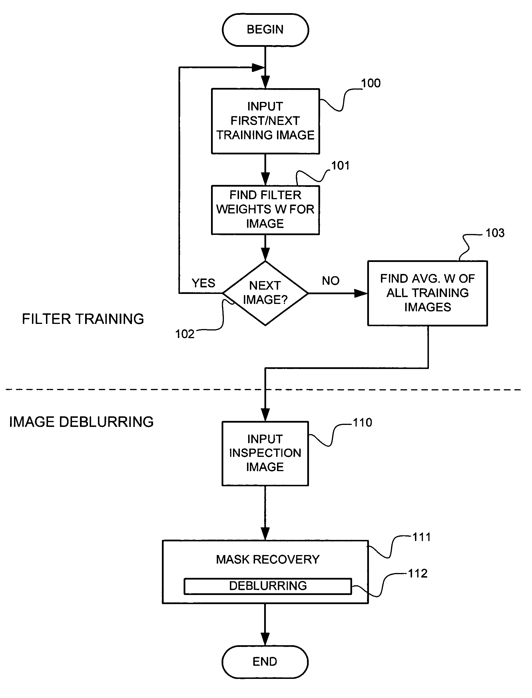
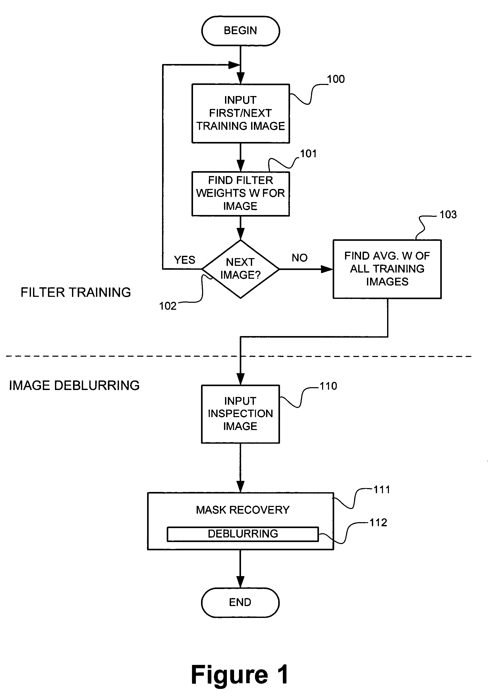
[0008]The invention comprises processes for determining and applying a deblurring filter that reduces inspection system distortion by compensating for the non-uniform frequency response of the inspection system.
[0009]In particular, an adaptive filter is determined empirically for an inspection system: one or more training images are obtained by the inspection system and the filter is determined from such images. In this way, the filter can adapt to the characteristics of each individual inspection system.
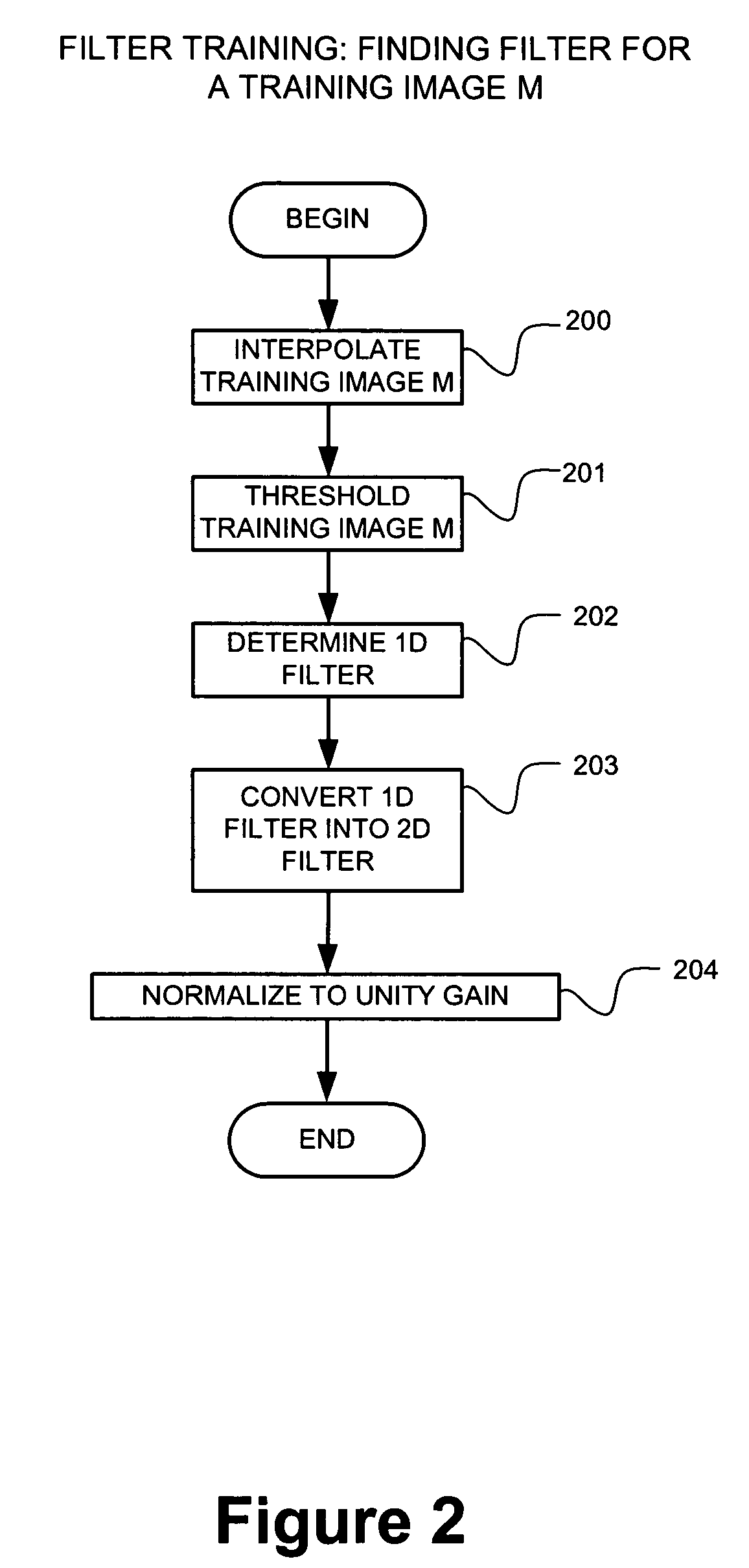
[0010]In general, an adaptive filter is derived by optimizing a suitable metric. An example adaptive filter, known as a Weiner filter, is determined and applied. A Weiner filter, when applied to an inspection image, minimizes the (sum of the) squared error between the filtered and “ideal” versions of that inspection image. The ideal image can be approximated, for training purposes, by thresholding the inspection image.
[0026]An advantage of a training image, compared with an arbitrary image, is that a simple thresholding of the training image can provide an estimate of the true location of the training image's edges. The thresholded training image can also be referred to as an “ideal” (or the desired) version of the training image since it may be the best estimate available of the true location of the training image's edges.
[0027]It can be desirable to interpolate a training image, to a higher resolution, prior to it being thresholded. Such interpolation can improve the accuracy with which thresholding finds the actual edges of a training image.

Problems solved by technology

For example, an inspection system can cause the spectral characteristic, of the received inspection image, to suffer greater attenuation as frequency increases.
This attenuation at higher frequencies tends to cause a loss of resolution in the inspection image, increasing the size of the smallest defects that can be detected.

Method used


Image

  • Method and apparatus for deblurring mask images
  • Method and apparatus for deblurring mask images
  • Method and apparatus for deblurring mask images

Examples


Embodiment Construction

[0052]Reference will now be made in detail to preferred embodiments of the invention, examples of which are illustrated in the accompanying drawings. Wherever possible, the same reference numbers will be used throughout the drawings to refer to the same or like parts.

[0053]

Table of Contents to Detailed Description1. Overview2. Further Details2.1 Interpolation2.2 Training Images2.3 One Dimensional Filter Determination2.4 One To Two Dimension Filter Conversion2.5 Image Deblurring2.6 Modified Approach: Separable Filter Training2.7 Training Image Recovery3. HARDWARE ENVIRONMENT

1. Overview

[0054]Deblurring, generally, is discussed in such texts as: A. K. Jain, “Fundamentals of Digital Image Processing,” Prentice Hall, Englewood Cliffs, N.J., 1989, ISBN 0-13-336165-9 (the Jain text). In particular, Chapter 8 of this text (pp.267-341) discusses “Image Filtering and Restoration.” The Jain text is herein incorporated by reference in its entirety.

[0055]The invention comprises processes for det...


PUM


Abstract

The invention comprises processes for determining and applying a deblurring filter that reduces inspection system distortion, of mask inspection images, by compensating for the non-uniform frequency response of the inspection system.In particular, an adaptive filter is determined empirically for an inspection system: one or more training images are obtained by the inspection system and the filter is determined from such images. In this way, the filter can adapt to the characteristics of each individual inspection system.An example adaptive filter, known as a Weiner filter, is determined and applied.

Description

FIELD OF THE INVENTION[0001]The present invention relates generally to filters for improving the resolution of mask images, and more particularly to using such filters to improve the ability to detect mask errors.BACKGROUND OF THE INVENTION[0002]As part of a process of manufacturing integrated circuits (ICs), inspection systems can be applied to search for mask defects. An example inspection system process is shown in FIG. 5A.[0003]The process of FIG. 5A begins with a photolithography mask (500) to be searched for defects. An inspection system is applied to the mask to obtain an inspection image (step 501). The inspection image is input to a “mask recovery” step (step 502) that produces an estimate of the mask. This mask estimate is then input to a photolithography simulator (step 503, that can also be referred to as a “stepper simulator”) that produces a simulated wafer image (504).[0004]A computer program can compare this simulated wafer image with a reference wafer image, searchi...

Claims


Application Information

Patent Timeline
Patent Type & Authority Patents(United States)
IPC IPC(8): G06K9/00
CPCG06T5/003G06T5/20G06T2207/20008G06T2207/20056G06T2207/20081
Inventor LUK-PAT, GERARD TERRENCECHANG, FANG-CHENG
Owner SYNOPSYS INC
Learn More