
Smoke detector

a detector and smoke technology, applied in the field of particle detectors, can solve the problems of large measurement stability demands, typically unoccupied obscuration detectors, etc., and achieve the effects of reducing the detection signal, reducing the background signal, and compromising the performance of the integrating spher

Active Publication Date: 2009-01-27
KIDDE IP HLDG
View PDF30 Cites 27 Cited by
  • Summary
  • Abstract
  • Description
  • Claims
  • Application Information

AI Technical Summary

Benefits of technology

"The present invention provides a particle detector with a chamber for receiving particles and a high reflectivity Lambertian surface for detecting radiation. The detector can be used for detecting particles of different colors, such as black or white smoke. The detector can also have multiple light sources for different wavelengths. The integrating sphere design allows for measurements to be made at different positions and is relatively insensitive to localized contamination. The addition of a second detector mounted in the sphere can compromise its performance but is necessary for detecting scattered light. The detector is advantageously located in the black part of the sphere to minimize the disturbance to the integrating sphere."

Problems solved by technology

Additionally, obscuration detectors typically are not housed within a chamber, as they have an emitter and a detector spaced at a substantial distance, such as 1 m, to provide adequate sensitivity.
Obscuration detectors that make a measurement of light transmission through the smoke are used extensively in beam smoke detectors but not in point smoke detectors because the path lengths available are relatively short, without complicated optical arrangements which can be prone to contamination, and this places great demands on the stability of the measurement.

Method used


Image

  • Smoke detector
  • Smoke detector
  • Smoke detector

Examples


Embodiment Construction

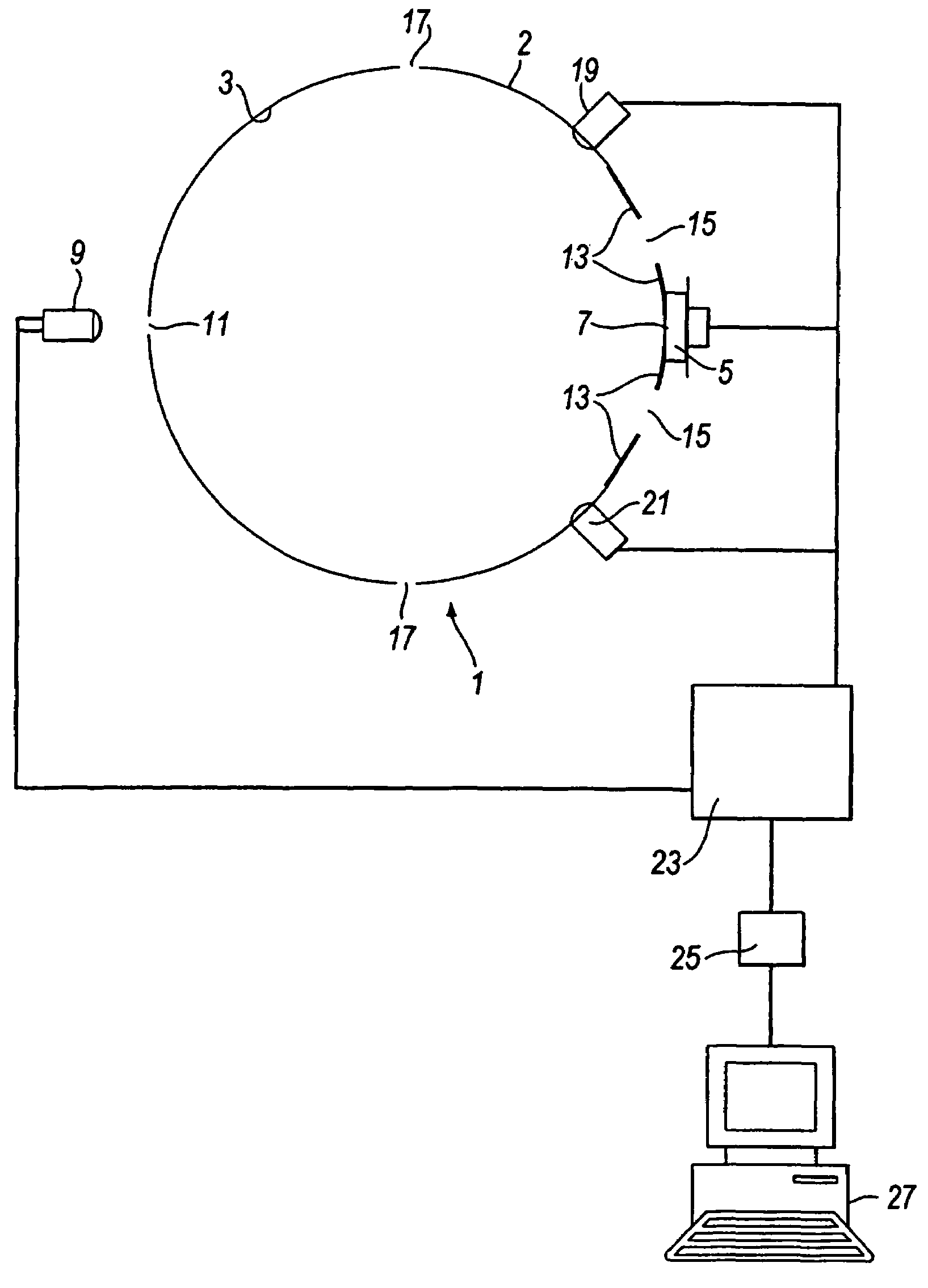
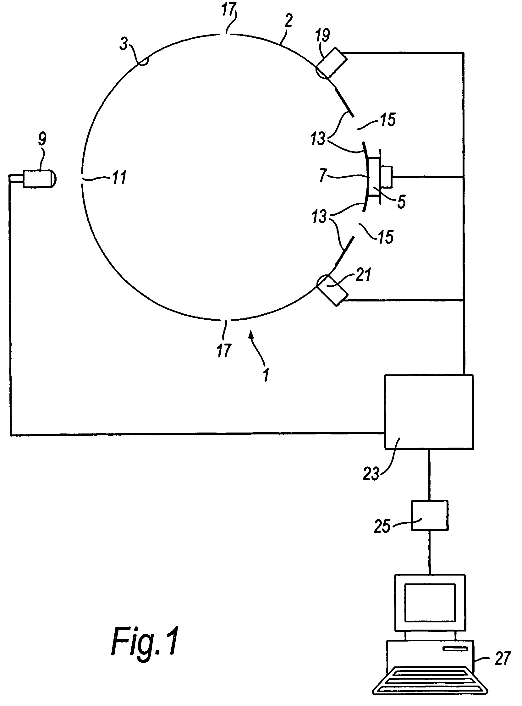
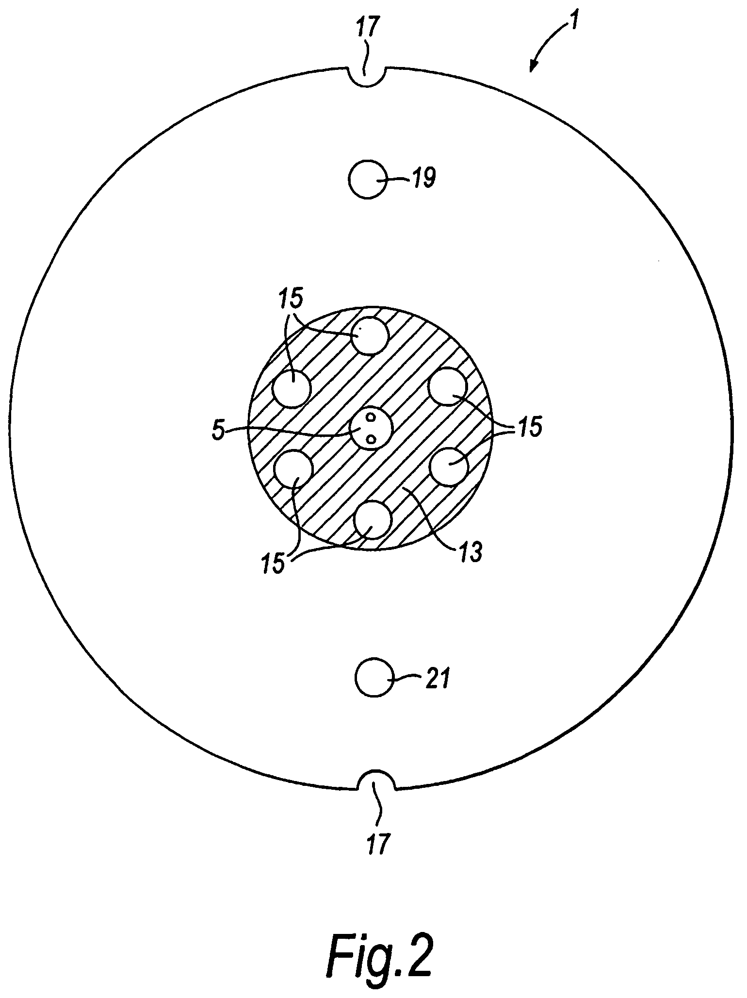
[0023]The smoke detector 1 comprises a hollow sphere 2 machined from aluminium alloy (or other suitable material) with an internal diameter in this example of 50 mm. Most of the internal surface 3 of the detector 1 is coated with a material in order to provide the surfaces so coated with a substantially high reflectivity (greater than 90%) Lambertian surface. A suitable material is barium sulphate. An integrating detector 5, for example a Centronic OSD5-1T silicon photodiode of 5 mm2 sensitive area, mounted on the exterior surface of the sphere 2, views a large portion of the white, inner surface 3 through a 5 mm diameter aperture 7. A scattering detector 9, for example an NSL710 silicon photodiode, is mounted on the exterior surface of the sphere 2 opposite the integrating detector 5 and is lensed so that it has a restricted viewing angle through aperture 11. A black painted region 13 of the internal surface of the sphere surrounds the integrating detector 5. One suitable black pai...


PUM

PropertyMeasurementUnit
reflectivityaaaaaaaaaa
distanceaaaaaaaaaa
lengthaaaaaaaaaa

Abstract

A smoke detector (1) has a spherical chamber (2) including a plurality of holes (15,17) for allowing smoke and other particles to enter the chamber. The majority of the internal surface (3) of the chamber (2) is covered with a high reflectivity Lambertian surface, that is a material that scatters incident light equally in all directions and at all wavelengths. The remaining portion of the internal surface (3) is coated with a light absorbing material (13) such as a matt black coating. A scatter sensor (9) is directed towards the absorbing coating (3), and an integrating detector (5) is configured to detect radiation directly from the entire Lambertian surface. A first LED (19) emits blue light into the chamber (2), and a second LED (21) emits infrared light into the chamber. Processing means (23, 25 and 27) are provided to analyse the signals from the detectors (5,9), including means for discriminating between signals from the sensors indicative of different frequencies of received radiation. The processing means can distinguish between different smoke types, such as white / grey smoke and black smoke, and can also distinguish between smoke and other particles.

Description

TECHNICAL FIELD[0001]The present invention relates to particle detectors and to a method of detecting particles—particularly, but not exclusively, smoke particles.BACKGROUND ART[0002]There are two detector types for detecting such particles. Obscuration, or direct, detectors have an emitter of suitable electromagnetic radiation, such as visible light, aligned with a detector for the radiation such that a beam of the radiation generated by the emitter shines directly into the detector through a volume in which the particles may be present. This type of detector thus measures the radiation lost from the beam, along a known path-length, across the volume containing the smoke, and is commonly measured as % / m of radiation lost. The radiation is lost from the beam by a combination of reflection, scattering and absorption in the smoke particles. Obscuration detectors typically work well for black smoke but are less sensitive to white or grey smoke. Additionally, obscuration detectors typic...

Claims


Application Information

Patent Timeline
Patent Type & Authority Patents(United States)
IPC IPC(8): G01N21/00G01N21/03G01N21/53G08B17/103G08B17/107G08B29/18
CPCG01N21/0303G01N21/534G08B17/103G08B17/107G08B29/183G01N2201/065G08B17/113
Inventor POWELL, BRIAN
Owner KIDDE IP HLDG
Learn More