
Rotary-piston engine and vehicle comprising an engine of this type

a technology of rotary pistons and engines, applied in the direction of machines/engines, liquid fuel engines, mechanical equipment, etc., can solve the problems of reduced efficiency, high wear and tear, and no grinding of grooves, and achieve the effect of simple construction

Inactive Publication Date: 2008-12-30
PERAVES
View PDF27 Cites 18 Cited by
  • Summary
  • Abstract
  • Description
  • Claims
  • Application Information

AI Technical Summary

Benefits of technology

[0010]The invention is based on the object of creating a rotary-piston engine of the above-mentioned type, which is improved particularly with reference to construction costs, operating characteristics, and wear and tear, in a simple construction, which does not have the above-mentioned disadvantages.
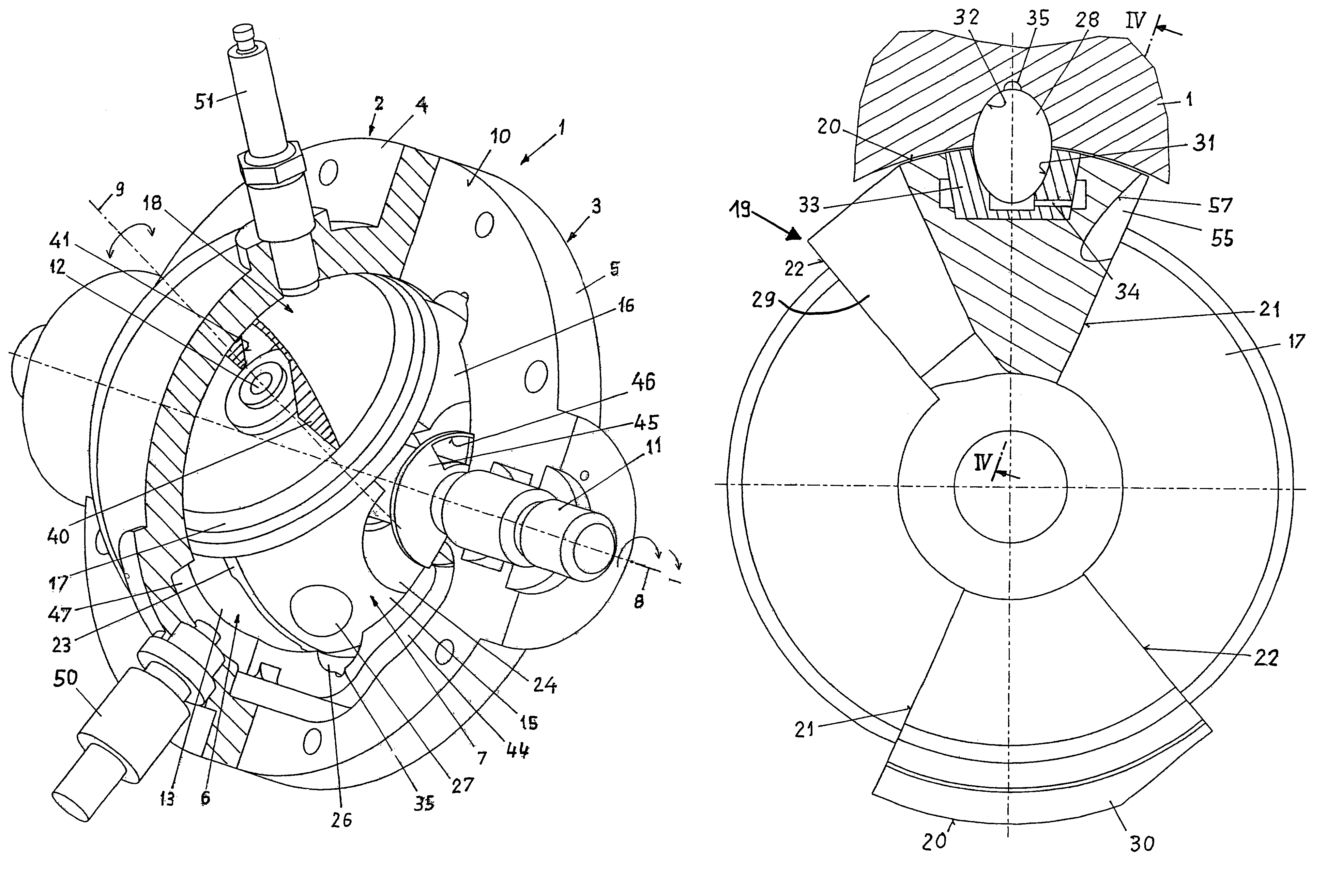
[0013]On the basis of the embodiment of the guide pans and of the guide groove according to the invention, a compact construction of the rotary-piston engine is achieved and a constructively simple guide configuration is created for the pistons, which combines the advantages of the low friction of a complex double-roller guide with the simplicity of a slide bearing guide and thus ensures a guiding of the pistons which is low in wear and tear.
[0014]With the embodiment according to the second solution of the object, the housing, in comparison with the embodiment with spherical guide members, can be embodied with a more narrow guide groove, which enables greater piston pivoting and thus the formation of chamber volumes which can be utilized to a greater extent, under the same material strain and with the same housing size.

Problems solved by technology

This roller journal or slide-bearing guide positioned in the piston has the disadvantage that, due to the tangential orientation of the guide members, two staggered rollers are necessary so that during a change of the guide force onto the opposite side, a grinding does not take place on the groove, caused by the reversal of the unrolling direction of rotation.
A slide bearing, in turn, causes high friction and thus reduced efficiency and high wear and tear on this most important part of the engine kinematics, which replaces the crankshaft of the lifting cylinder motor.
A further disadvantage of this guide configuration is seen in that the roller journals are mounted on the piston backsides, protruding beyond them, and that the guide grooves at the housing side, which work as antechamber walls for a pre-compression, are not covered against the piston backsides.
Furthermore, the lubricating fluid necessary for the lubrication of the rollers and guide grooves can reach through overflow channels into the operating chamber partly as leakage fluid and can lead to a high consumption of lubricating fluid as well as to two-stroke-like blue-smoke in the exhaust gas, whereby it is difficult to fulfill today's motor vehicle exhaust gas standards and it becomes difficult or impossible to use the rotary-piston engine several times.
However, because the pivoting movements of the piston halves are three-dimensional movements, equalized masses and moments are not sufficient here for a quiet run, contrary to lifting cylinder and / or rotary engines.
It is considered disadvantageous that a preheating of the fresh mixture can lead to power loss and knocking problems and is only suitable for a small power density.

Method used


Image

  • Rotary-piston engine and vehicle comprising an engine of this type
  • Rotary-piston engine and vehicle comprising an engine of this type
  • Rotary-piston engine and vehicle comprising an engine of this type

Examples


Embodiment Construction

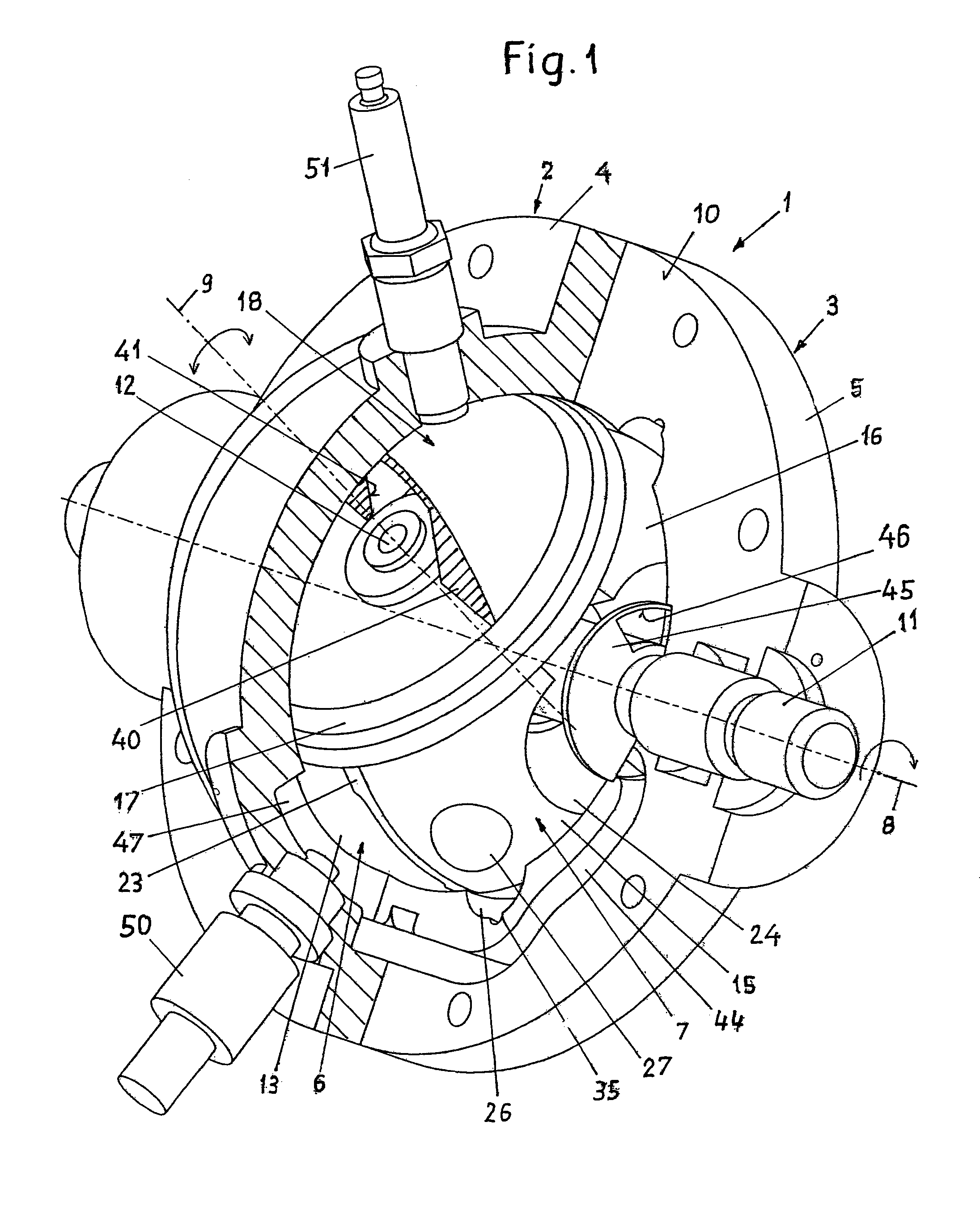
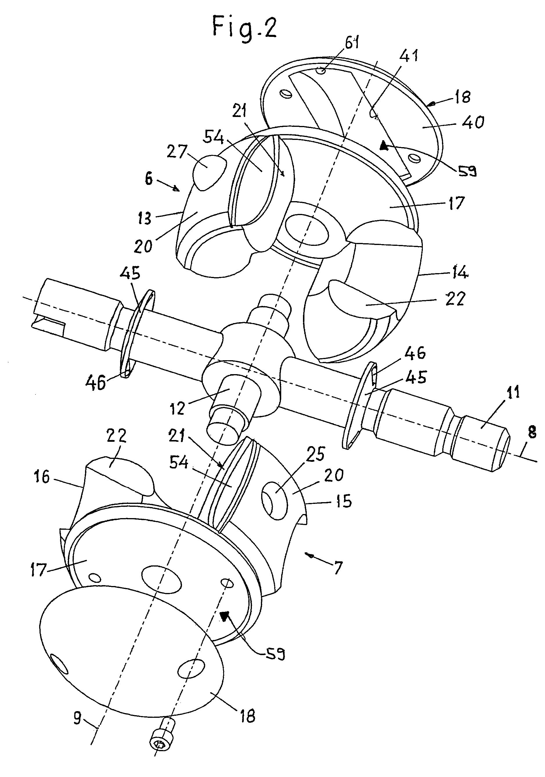
[0030]The rotary-piston engine according to FIG. 1, which is illustrated as a motor with externally-supplied ignition, has an essentially spherical housing 1 with spherical inner surface, which is divided by a junction plane 10 into two housing halves 2 and 3, which are connected with one another via a ring flange 4 or 5 and non-illustrated screws. In the housing 1, two two-armed rotary pistons 6 and 7 are located, which together rotate about a rotational axis 8 arranged at the center of the housing and thereby execute pivoting displacements back and forth in opposite directions overlapping the rotational movement about a pivoting axis 9 running perpendicular to the rotational axis 8. The rotational axis 8 is formed by a shaft 11, which is supported on both sides in the housing 1 and which is embodied as a pinion shaft.

[0031]The rotary pistons 6 and 7 each have two pistons 13 and 14, or 15 and 16, respectively, located essentially diametrically opposite to one another in the form of...


PUM


Abstract

A rotary-piston engine includes at least two rotary pistons, which are located in an essentially spherical housing and which rotate in common about a rotational axis running through the center of the housing, each of the rotary pistons comprising two pistons that are interconnected in a fixed manner, lie diametrically opposite the center of the housing and execute pivoting displacements back and forth in opposite directions about a pivoting axis running perpendicular to the rotational axis, during their rotation. To control the pivoting displacements, the engine is provided with loose spherical or ellipsoidal rotational bodies, which are rotatably mounted in the sliding surfaces of the pistons in respective guide sockets that are hemispherical or ellipsoidal and which engage in at least one guide groove that is configured in the housing. The groove has an essentially hemispherical or ellipsoidal profile.

Description

BACKGROUND OF THE INVENTION[0001]The invention relates to a rotary-piston engine comprising at least two two-armed rotary pistons, which are located in an essentially spherical housing and which rotate in common about a rotational axis running through the center of said housing. Each of the rotary pistons comprises two pistons in the form of piston arms that are interconnected in a fixed manner, lie essentially diametrically opposite to each other with respect to the center of the housing and execute pivoting displacements back and forth in opposite directions about a pivoting axis running perpendicular to the rotational axis, during their rotation, whereby guide members are embodied on at least two pistons, which engage in at least one guide groove embodied in the housing for controlling the pivoting displacements.[0002]Furthermore, the invention pertains to a vehicle with such a rotary-piston engine.[0003]Rotary piston-engines belong to the category of combustion engines, where th...

Claims


Application Information

Patent Timeline
Patent Type & Authority Patents(United States)
IPC IPC(8): F02B33/44F01C3/06F01C9/00F01C21/08F01C21/10
CPCF01C9/005F01C21/104F01C9/00F01C21/08F01C21/10F01D21/12
Inventor WAGNER, ARNOLD
Owner PERAVES
Learn More