
Actuator mechanism for shift motors of a transmission

a technology of shift motor and actuator mechanism, which is applied in mechanical actuation clutches, gearing, transportation and packaging, etc., can solve the problems of complex mechanisms that require order and introduce potential failure modes, and achieve optimal shift flexibility and minimize the length of the fork mechanism

Inactive Publication Date: 2008-12-23
FORD GLOBAL TECH LLC
View PDF10 Cites 26 Cited by
  • Summary
  • Abstract
  • Description
  • Claims
  • Application Information

AI Technical Summary

Benefits of technology

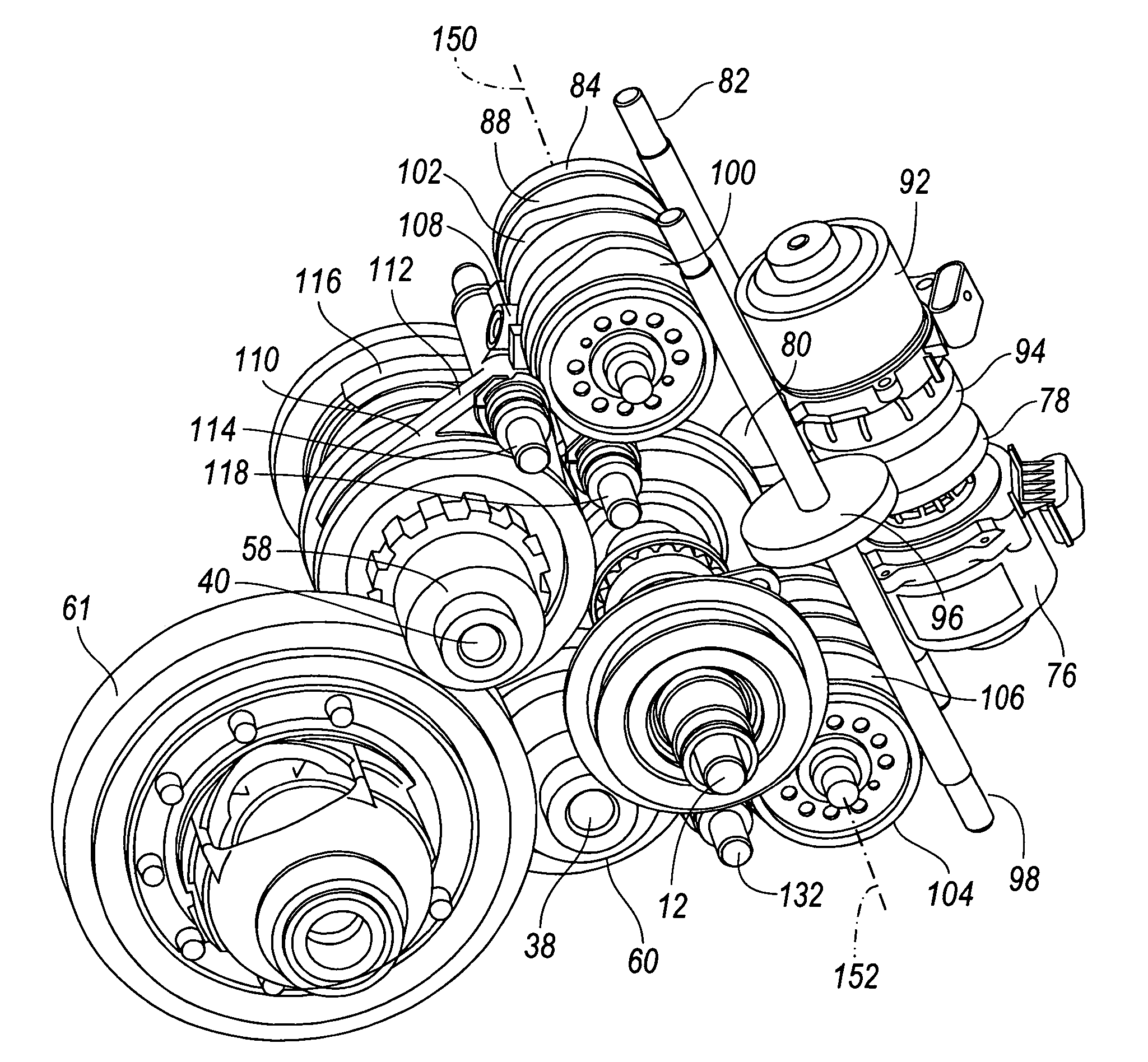
The patent describes a system for actuating couplers in a motor vehicle transmission. The system includes four actuator drums, one for each gear, and an electric motor for controlling their engagement and disengagement. The actuator drums are located close to the shift forks, which minimizes the length of the fork mechanism and allows separate control of odd and even gears. The system provides optimal shift flexibility and allows for separate control of gear engagement and disengagement. The patent also describes different embodiments of the system, including one with two motors and gearing, and another with four motors and gearing.

Problems solved by technology

Unfortunately, odd and even gears tend to be located at opposite ends of the gearbox, with both odd and even gears along each side.
But complex mechanisms are required in order to enable three gear step shifts, i.e., six-three, five-two downshifts, with that arrangement.
These complex mechanisms introduce potential failure modes.

Method used


Image

  • Actuator mechanism for shift motors of a transmission
  • Actuator mechanism for shift motors of a transmission
  • Actuator mechanism for shift motors of a transmission

Examples


Embodiment Construction

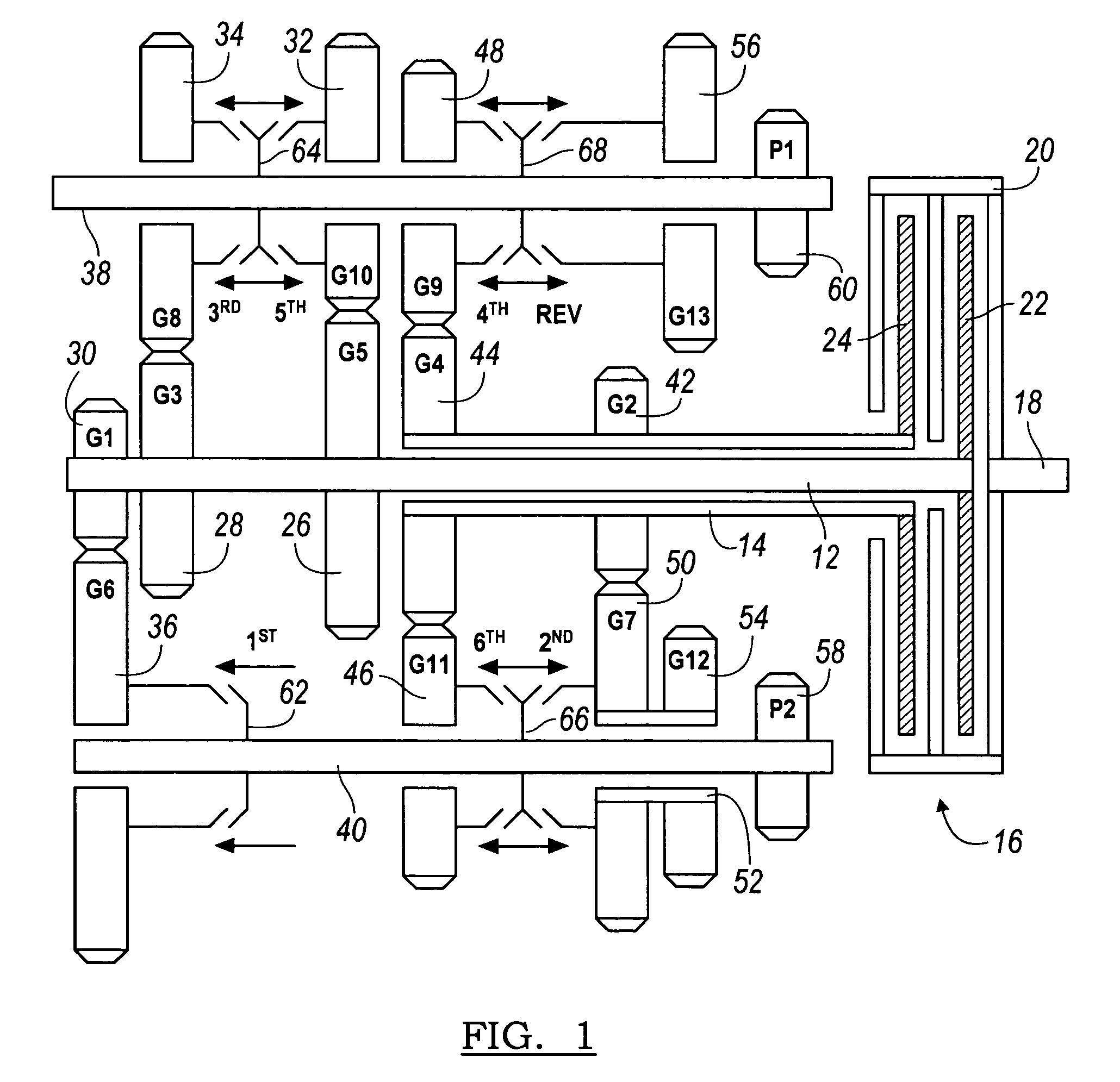
[0023]Referring now to FIG. 1, a transmission 10 includes a first input shaft 12, and a second input shaft 14. Input shaft 14 is a sleeve shaft surrounding input shaft 12. A dual clutch mechanism 16 produces a drive connection between the crankshaft 18 of an engine, an electric motor shaft, or the shaft of another power source to the first and second input shafts 12, 14. The clutch mechanism 16 includes a rotor 20, which is driveably connected to shaft 18 and is alternately driveably connected to and disconnected from input shaft 12 when clutch 22 is engaged and disengaged, respectively. Rotor 20 is alternately driveably connected to and disconnected from input shaft 14 when clutch 24 is engaged and disengaged, respectively.

[0024]Input shaft 12 supports pinions 26, 28, 30, which are secured to shaft 12. Each pinion 26, 28, 30 is in meshing engagement with a corresponding gear 32, 34, 36, gears 32, 34 being journalled on a layshaft 38, gear 36 being journalled on a layshaft 40. Simil...


PUM


Abstract

A system for actuating gear changes in a motor vehicle transmission includes an electric motor including a motor shaft supported for rotation about an axis, first and second actuator drums supported for rotation substantially parallel to the axis, and a drive mechanism including a first power path driveably connecting the motor shaft and the first drum, and a second power path driveably connecting the motor shaft and the second drum.

Description

CROSS-REFERENCE TO RELATED APPLICATION[0001]This application is a continuation-in-part of the co-pending U.S. patent application Ser. No. 11 / 374,354, filed Mar. 13, 2006.BACKGROUND OF THE INVENTION[0002]The preferred embodiment relates generally to an apparatus for actuating couplers that engage gears in a transmission.[0003]A twin clutch transmission must have some mechanism to move shift forks to engage gears. Shift drums convert rotary motion of a drum into appropriate linear motion of a set of shift forks. For optimal shift flexibility, it is best to have separate control of the engagement of the odd-numbered gears and the even-numbered gears. However, it is also advantageous to locate the shift drum physically close to the shift forks. Unfortunately, odd and even gears tend to be located at opposite ends of the gearbox, with both odd and even gears along each side. For example, the first, second and sixth gears may be located on one side of the gearbox, and the third, fourth, a...

Claims


Application Information

Patent Timeline
Patent Type & Authority Patents(United States)
IPC IPC(8): F16H59/00F16H61/00F16H63/00
CPCF16H3/006F16H63/18F16H61/32Y10T74/19228F16H61/688F16H2003/0931F16H2200/0052F16H2063/025Y10T74/19395Y10T74/19223Y10T74/19251Y10T74/19288Y10T74/19233Y10T74/19405Y10T74/19279
Inventor BALDWIN, REIDJANSON, DAVID
Owner FORD GLOBAL TECH LLC
Learn More