Method of detecting displacement of exposure position marks
a technology of exposure position marks and displacement, which is applied in the direction of instruments, photomechanical equipment, and semiconductor/solid-state device details, etc., can solve the problems of inability to eliminate measurement fluctuations, aberration of the lenses used in the measurement optical system, and not always obtained same detection results, etc., to improve the precision with which displacement can be detected. , the effect of high precision
- Summary
- Abstract
- Description
- Claims
- Application Information
AI Technical Summary
Benefits of technology
Problems solved by technology
Method used
Image
Examples
first embodiment
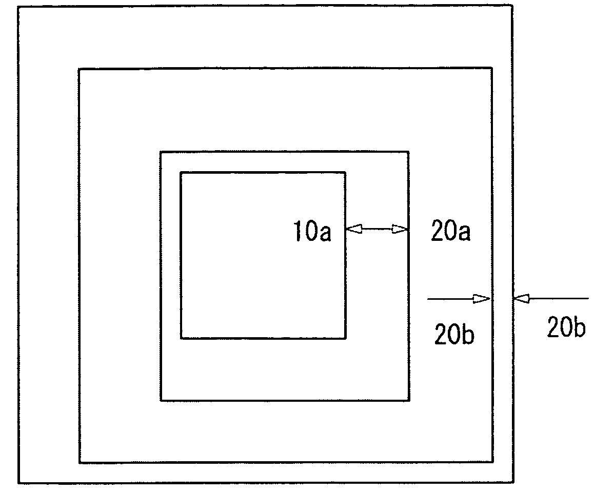
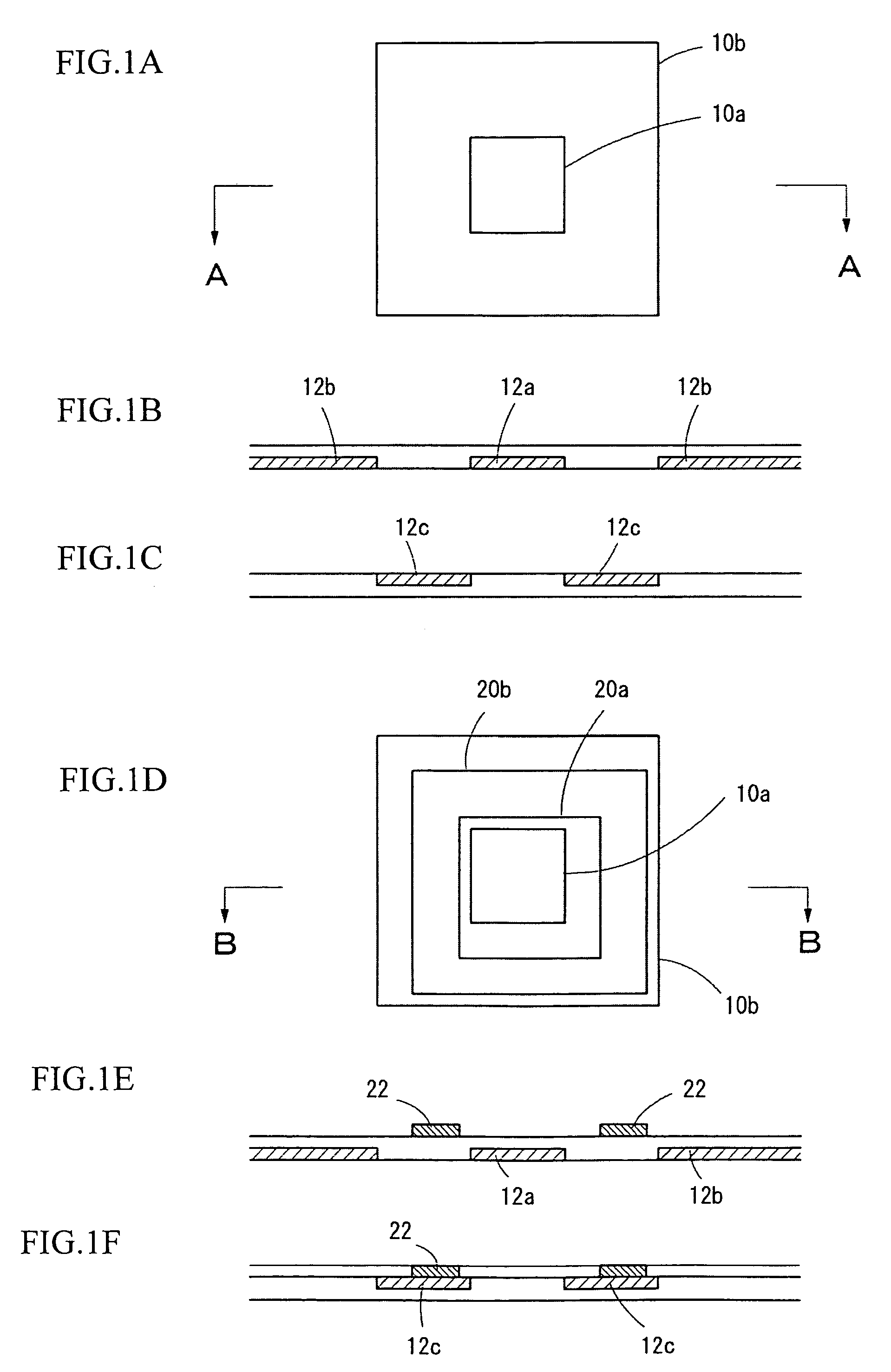
[0035]FIGS. 1A to 1F show examples of exposure position marks that are formed in a former process and in a latter process to enable displacement of the marks to be detected, according to the method of detecting displacement of exposure position marks according to the present invention.
[0036]FIG. 1A shows the exposure position marks formed in the former process. These exposure position marks are formed so that the center positions of two, (i.e., a large and a small) square patterns 10a and 10b match and are disposed so that the edges of the patterns 10a and 10b are parallel.
[0037]FIGS. 1B and 1C are cross-sectional views taken along the line A-A in FIG. 1A and show examples of where the square patterns 10a and 10b are formed on a base layer. FIG 1B shows an example where a pattern 12a that forms the inner square pattern 10a and a pattern 12b that forms the outer square pattern 10b are formed. FIG. 1C shows an example where a frame-shaped pattern 12c is formed on the base layer to for...
second embodiment
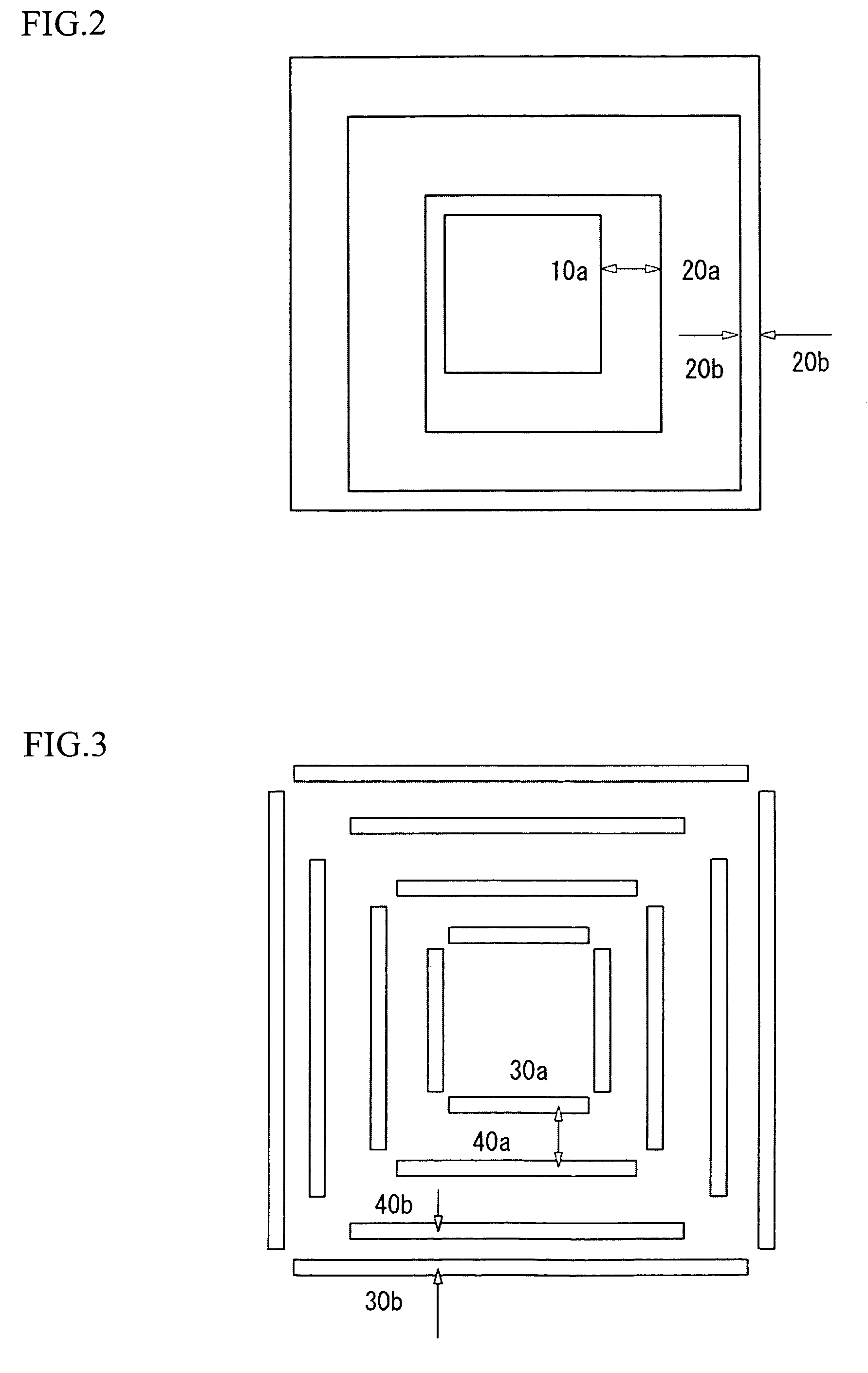
[0051]FIG. 3 shows another example of exposure position marks used by the method of detecting a displacement of exposure position marks according to the present invention. The exposure position marks used in the present embodiment are composed of bar-shaped patterns that are disposed in quadrangular arrangements where a quadrangular arrangement of bar-shaped patterns 30a on the inside and a quadrangular arrangement of bar-shaped patterns 30b on the outside are used as the first pattern and a quadrangular arrangement of bar-shaped patterns 40a on the inside and a quadrangular arrangement of bar-shaped patterns 40b on the outside are used as the second pattern.
[0052]The patterns 30a and 30b are formed in square arrangements so that the center positions of the respective quadrangular arrangements match and the edges of the arrangements are parallel. The patterns 40a and 40b are also formed in square arrangements so that the center positions of the respective quadrangular arrangements m...
third embodiment
[0055]FIG. 4 shows another example of exposure position marks used by the method of detecting a displacement of exposure position marks according to the present invention. The exposure position marks in the present embodiment are an example where square patterns 50a and 50b that are the first pattern and square patterns 60a and 60b that are the second pattern are formed with the same shape and the same size and are disposed in a crisscross arrangement.
[0056]The first pattern and the second pattern are exposure position marks that are formed in different steps. The first pattern and the second pattern are formed so that the center of respective center positions of the square patterns 50a and 50b that are the first pattern and the center of the respective center positions of the square patterns 60a and 60b that are the second pattern match.
[0057]When detecting the displacement, image recognition is carried out for the square patterns 50a and 50b that form the first pattern and the squ...
PUM
 Abstract
Description
Claims
Application Information
 - R&D
- Intellectual Property
- Life Sciences
- Materials
- Tech Scout
- Unparalleled Data Quality
- Higher Quality Content
- 60% Fewer Hallucinations
Browse by: Latest US Patents, China's latest patents, Technical Efficacy Thesaurus, Application Domain, Technology Topic, Popular Technical Reports.
© 2025 PatSnap. All rights reserved.Legal|Privacy policy|Modern Slavery Act Transparency Statement|Sitemap|About US| Contact US: help@patsnap.com


