
Active 90-degree phase shifter with LC-type emitter degeneration and quadrature modulator IC using the same

a 90-degree phase shifter and quadrature modulator technology, applied in the direction of pulse manipulation, pulse modulation, pulse technique, etc., can solve the problems of high implementation loss, difficult integration in the integrated circuit, complex design, etc., and achieve the effect of reducing the leakage amount of the carrier wave and low implementation loss

Inactive Publication Date: 2008-12-09
NAT SUN YAT SEN UNIV
View PDF3 Cites 10 Cited by
  • Summary
  • Abstract
  • Description
  • Claims
  • Application Information

AI Technical Summary

Benefits of technology

[0008]The present invention is different form other existing 90-degree phase shifters in that resistors used by existing 90-degree phase shifters are real resistors. Because the 90-degree phase shifter of the present invention dose not use real resistors as constituting elements, thereby it has the advantage of low implementation loss, such that the required carrier wave power of the local oscillating source can be effectively decreased in order to reduce the leakage amount of the carrier wave.

Problems solved by technology

In addition to the above two methods, LC high pass / low pass filter method, RC full pass filter method, ring oscillator method, multi-phase filter method, etc. can also be used, however they still have the disadvantages of high implementation loss, difficult to be integrated in an integrated circuit, complex design, the difficulty of precise control of the phase shift, high current consumption, etc.
In summary, the common disadvantage for the above design methods is high implementation loss, it is because resistors used by existing 90-degree phase shifters are real resistors.

Method used


Image

  • Active 90-degree phase shifter with LC-type emitter degeneration and quadrature modulator IC using the same
  • Active 90-degree phase shifter with LC-type emitter degeneration and quadrature modulator IC using the same
  • Active 90-degree phase shifter with LC-type emitter degeneration and quadrature modulator IC using the same

Examples


Embodiment Construction

[0019]Although the present invention will be described in considerable detail with reference to accompanying figures containing preferred embodiments thereof, however prior to this description, it should be understood that those skilled in the art can easily make changes to the present invention described herein and the same performance as the present invention is obtained. Therefore, it is to be understood that the following description is a general disclosure to those skilled in the art and is not restrictive of the present invention.

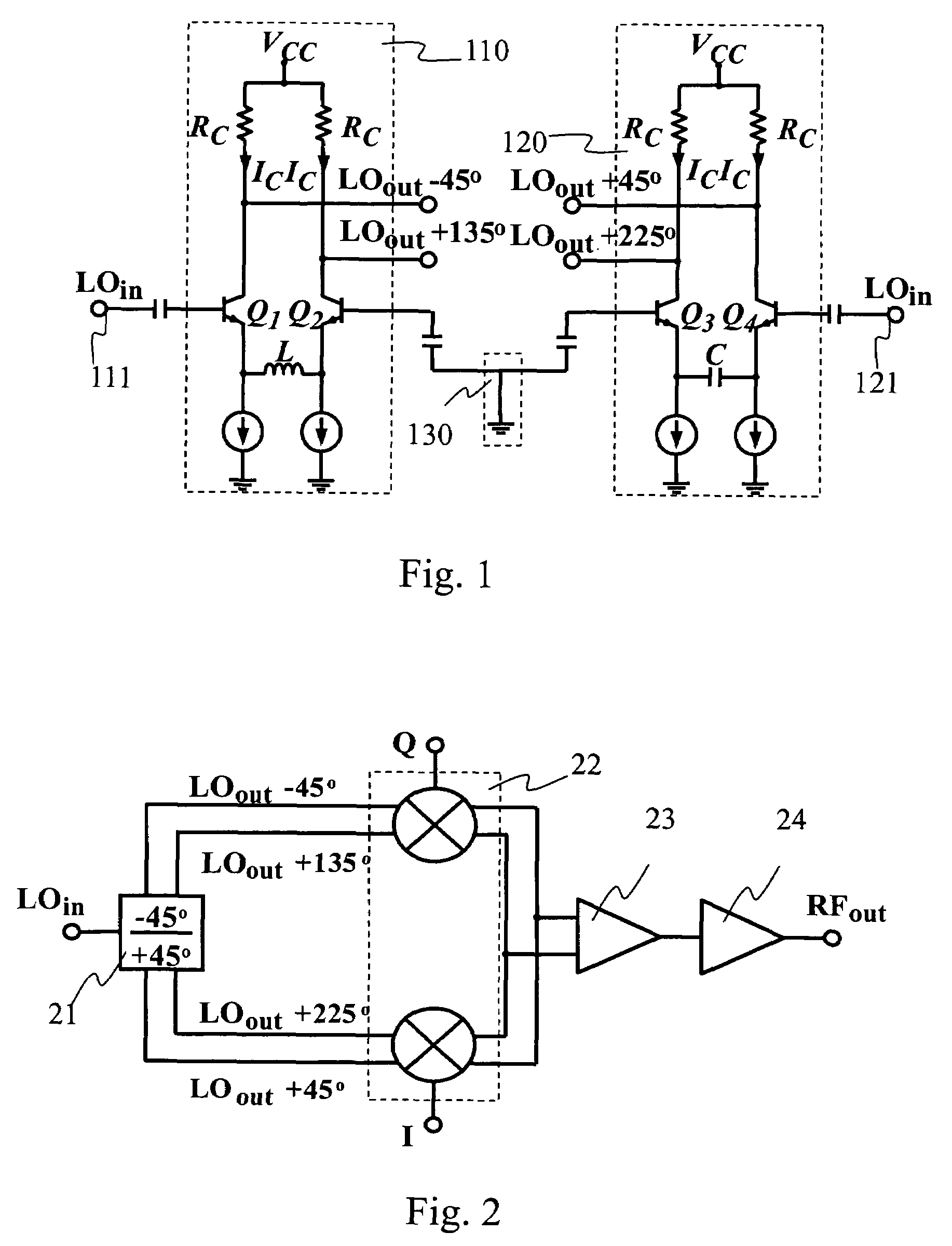
[0020]Referring to FIG. 2, a structural view of a quadrature modulator integrated circuit of the present invention is shown. This quadrature modulator is consisted of a novel 90-degree phase shifter 21, two doubly balanced wave mixers 22, one differential single-ended converter 23 and one output buffer 24. The 90-degree phase shifter 21 generates the phase shift showed in FIG. 2, wherein LOout−45° has a delaying phase of 45-degree compared with LOin, ...


PUM


Abstract

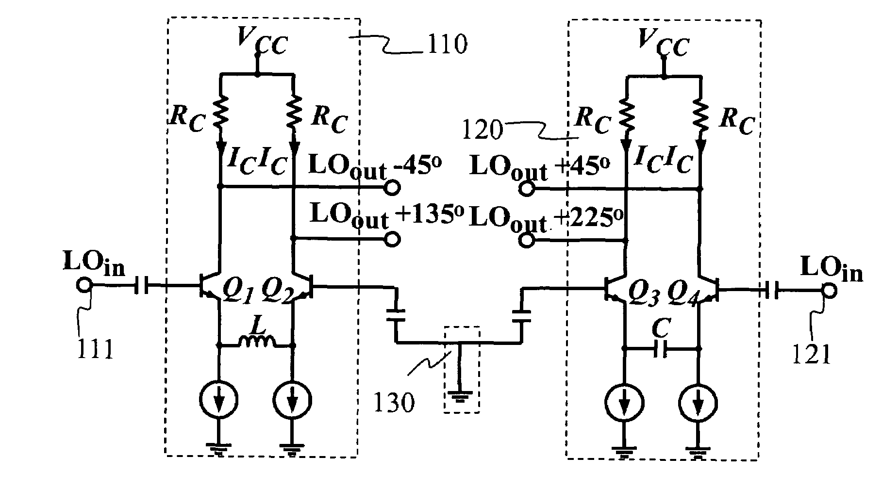
An active 90-degree phase shifter with LC-type emitter (source) degeneration is provided, which is practiced in an integrated circuit. The phase shifter comprises a first differential amplifier, having one first signal output end and comprising an inductor, a first transistor and a second transistor, wherein the inductor is connected to the emitters (sources) of the first and the second transistors; and a second differential amplifier, having one second signal output end and comprising a capacitor, a third transistor and a fourth transistor, wherein the capacitor is connected to the emitters (sources) of the third and the fourth transistors. Wherein the bases (gates) of the first and the fourth transistors are signal input ends, and the bases (gates) of the second and the third transistors are coupled together. Further, the phase shift between one signal input end and the first signal output end or the second signal output end is determined by the intrinsic resistors of the transistors, the inductor and the capacitor.

Description

BACKGROUND OF THE INVENTION[0001]1. Field of the Invention[0002]The present invention relates to a design method for a phase shifter, especially to a 90-degree phase shifter used by a quadrature modulator integrated circuit. The present invention implements a design method for a 90-degree phase shifter required by a quadrature modulator integrated circuit by using a RL-RC type microwave network formed by the intrinsic resistors of the transistors of differential amplifiers combined with emitter (source)-degenerative inductor and capacitor.[0003]2. Description of the Related Art[0004]The performance of a quadrature modulator is relative to the precision of the 90-degree phase shift as well as the low amplitude disharmony of the signal from the local oscillator. Many methods for implementing 90-degree phase shift have been suggested now, such as frequency doubling (for example, see H. M. Rein, R. Reimann, and L. Schmidt, “A 3 Gb / s bipolar phase shifter and AGC amplifier,” in IEEE Int....

Claims


Application Information

Patent Timeline
Patent Type & Authority Patents(United States)
IPC IPC(8): H04L27/20
CPCH03C3/403H04L27/20
Inventor HORNG, TZYY-SHENGWU, JIAN-MINGHAN, FU-YILIN, JENSHAN
Owner NAT SUN YAT SEN UNIV
Learn More