Micro-wave tube with mechanical frequency tuning

a technology of mechanical frequency tuning and micro-wave tubes, which is applied in the direction of transit-tube circuit elements, electrical devices, electric discharge tubes, etc., can solve the problems of severe degradation of tube performance, and achieve the effects of fast modulation of parameters, easy automation, and rapid external control

Inactive Publication Date: 2008-11-25
COMMISSARIAT A LENERGIE ATOMIQUE ET AUX ENERGIES ALTERNATIVES
View PDF5 Cites 1 Cited by
  • Summary
  • Abstract
  • Description
  • Claims
  • Application Information

AI Technical Summary

Benefits of technology

[0016]According to a second embodiment of the invention, the mechanical means for displacing rings comprise a set of electrical contacts between the rings, at least one set of pins, each pin being firmly connected to a ring, the tube being provided with at least one longitudinal slit through which pins can pass in the wall of the tube, a ring external to the tube comprising at least one set of slits, each slit in the outer ring allowing the passage of at least one pin, the slits in a set of slits having a different inclination for each ring so as to maintain a periodicity for the different rings during displacement of the rings.
[0020]The invention has the advantage that the frequency F of the emitted electromagnetic wave can be varied within a large variation range, namely a few tens of percent, while maintaining amplification performances of the electromagnetic wave existing in the power sources working at fixed frequency.
[0023]Advantageously, this integrated system enables fast modulation of parameters, namely the frequency and power of the radio frequency signal. The system can easily be automated and can be quickly externally controlled without needing to modify operation of the electron beam.
[0024]This integrated system can be particularly well adapted to BWO type hyper frequency tubes. It then replaces periodic structures in place and / or inserts. It is also easily adaptable to other types of tubes. It may also be associated with other systems provided to enable variation of the output frequency of the signal. It can then advantageously be used to increase the efficiency and the operating range of the system.

Problems solved by technology

In general, the microwave tubes mentioned above are optimised to work at a fixed frequency and known means of varying the frequency of the tube always cause a severe degradation of tube performances.

Method used


Image

  • Micro-wave tube with mechanical frequency tuning
  • Micro-wave tube with mechanical frequency tuning
  • Micro-wave tube with mechanical frequency tuning

Examples


first embodiment

[0033]the invention is shown in FIGS. 3A and 3B.

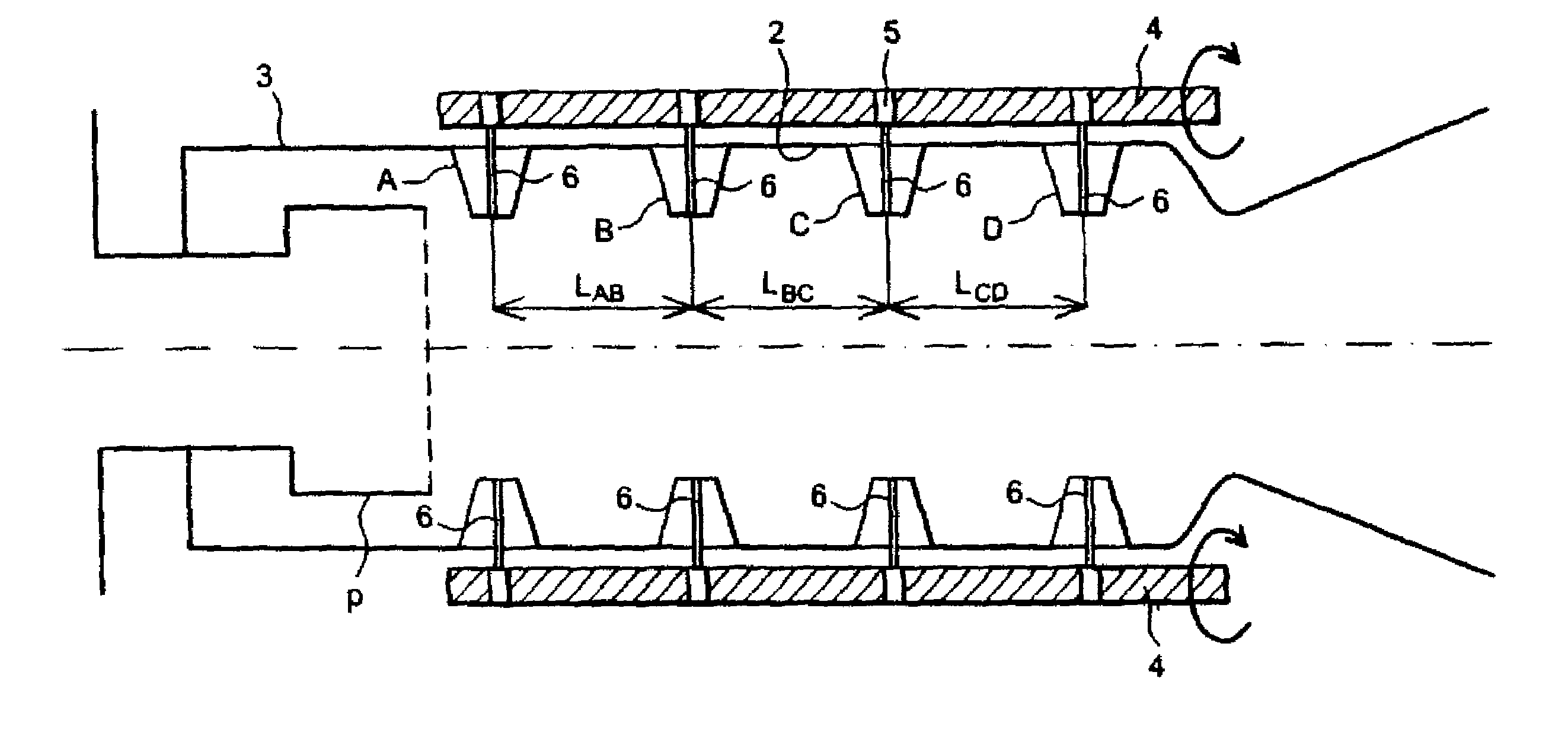
[0034]The electromagnetic structure for adjustment of the frequency of the microwave tube comprises a fixed part and a mobile part.

[0035]The fixed part is composed of the longitudinal wall 3 of the tube in which at least one guide slit G (FIG. 3B) is formed.

[0036]The mobile part comprises:[0037]at least one lead screw 4,[0038]nuts 5 installed on the lead screw 4,[0039]a set of rods 6 and a set of rings (for example four rings A, B, C, D), each rod 6 firmly fixing a nut to a ring, the rings being installed on the inside of the wall 3 of the tube,[0040]electrical contacts 2 (FIG. 3A) between the rings.

[0041]The guide slit(s) G enable passage of rods 6 in the longitudinal wall 3 of the tube so as to connect the nuts 5 to the rings as best shown in FIG. 3B. A ring seen in section (see FIGS. 3A, 3B) may for example be profiled like a rim.

[0042]During the frequency adjustment, the lead screw is moved in rotation, which drives the nuts 5, the...

second embodiment

[0049]FIGS. 4A and 4B show the invention.

[0050]According to the second embodiment of the invention, the variation of the periodicity of the rings is based on the rotation of a ring equipped with slits inside which pins connected to periodic corrugated structures are able to move. The inclination of these slits is such that it enables a specific interval to be maintained.

[0051]The tube 3 is the same as the tube in the previous assembly. Each ring A, B, C, D placed inside the tube 3 is fixed to a pin 7. A pin 7 moves inside two slits located on two independent parts, namely the fixed tube 3 and an outer ring 8. A first slit 9 placed on the fixed tube 3 only enables ring translation movements in the longitudinal direction of the tube. A set of slits 10 placed on the outer ring 8 fixes the range of variations of the period of the periodic structure. They correspond to the different pitches of the lead screw 4 of the previous assembly and perform the same function. The slits 10 (FIG. 4B)...


PUM


Abstract

This invention relates to a microwave tube (3) for generation of an electromagnetic wave with frequency F, the tube comprises mechanical means for varying the frequency F composed of a set of rings (A, B, C, D) defining a periodic structure inside the tube and mechanical means (4, 5, 2, G) for displacing rings with respect to each other while maintaining a periodicity for periodic structure during displacement of the rings.

Description

CROSS-REFERENCE TO RELATED APPLICATION[0001]This application claims priority based on International Patent Application No. PCT / FR03 / 01960, entitled “Microwave Tube With Mechanical Frequency Tuning” by Jehan VANPOPERYNGHE and Jean-Paul PRULHIERE, which claims priority of French Application No. 02 07849, filed on Jun. 25, 2002, which was not published in English.TECHNICAL DOMAIN AND PRIOR ART[0002]The invention relates to a microwave tube with mechanical frequency tuning.[0003]The invention is used in a particularly advantageous application in the domain of electronic tubes for generating and / or amplifying radio electric signals.[0004]The principle of a microwave tube according to known art is shown in FIG. 1. The microwave tube comprises:[0005]a source of electrons composed of an emission cathode K and an anode electron gun CA to form an electron beam F,[0006]a focusing coil L surrounding the electron beam and producing a continuous axial magnetic field B so as to prevent the electro...

Claims


Application Information

Patent Timeline
Patent Type & Authority Patents(United States)
IPC IPC(8): H01J23/213H01J23/207
CPCH01J23/207
Inventor VANPOPERYNGHE, JEHANPRULHIERE, JEAN-PAUL
Owner COMMISSARIAT A LENERGIE ATOMIQUE ET AUX ENERGIES ALTERNATIVES
Why Eureka
Try Eureka