
Quartz Crystal Device Using At-Cut Quartz Substrate and Manufacturing the Same

a quartz crystal and at-cut technology, applied in piezoelectric/electrostrictive transducers, transducer types, generators/motors, etc., can solve the problems of high cost of unreasonable and significant stress might be applied to the package or at-cut quartz crystal pieces, and achieve the effect of less cos

Inactive Publication Date: 2011-10-06
NIHON DEMPA KOGYO CO LTD
View PDF3 Cites 15 Cited by
  • Summary
  • Abstract
  • Description
  • Claims
  • Application Information

AI Technical Summary

Benefits of technology

[0016]According to the present invention, there are provided a surface-mounting type quartz crystal device which costs less and is unlikely to be broken and insusceptible to changes in frequency due to changes in temperature.

Problems solved by technology

However, although the quartz crystal device disclosed in the 2009-2324495 uses glass whose coefficient of thermal expansion is close to that of the quartz crystal piece, its coefficient of thermal expansion is not equal to that of the quartz crystal piece.
Thus, when soldering the quartz crystal device to a printed circuit board, an unreasonable and significant stress might be applied to the package or the AT-cut quartz crystal piece due to a significant temperature change.
Although it can be considered to use a package made of AT-cut quartz crystal piece instead of the glass package having a similar coefficient of thermal expansion, the AT-cut quartz crystal piece costs high because of influences of a cutting angle from an artificial quartz crystal.

Method used


Image

  • Quartz Crystal Device Using At-Cut Quartz Substrate and Manufacturing the Same
  • Quartz Crystal Device Using At-Cut Quartz Substrate and Manufacturing the Same
  • Quartz Crystal Device Using At-Cut Quartz Substrate and Manufacturing the Same

Examples


Embodiment Construction

[0027]Hereinafter, the preferred embodiments of the present invention will be described in detail with reference to the accompanying drawings. In the meantime, the scope of the present invention is not limited to embodiments described here unless it is described that the present invention is limited to any particular embodiments in a following description.

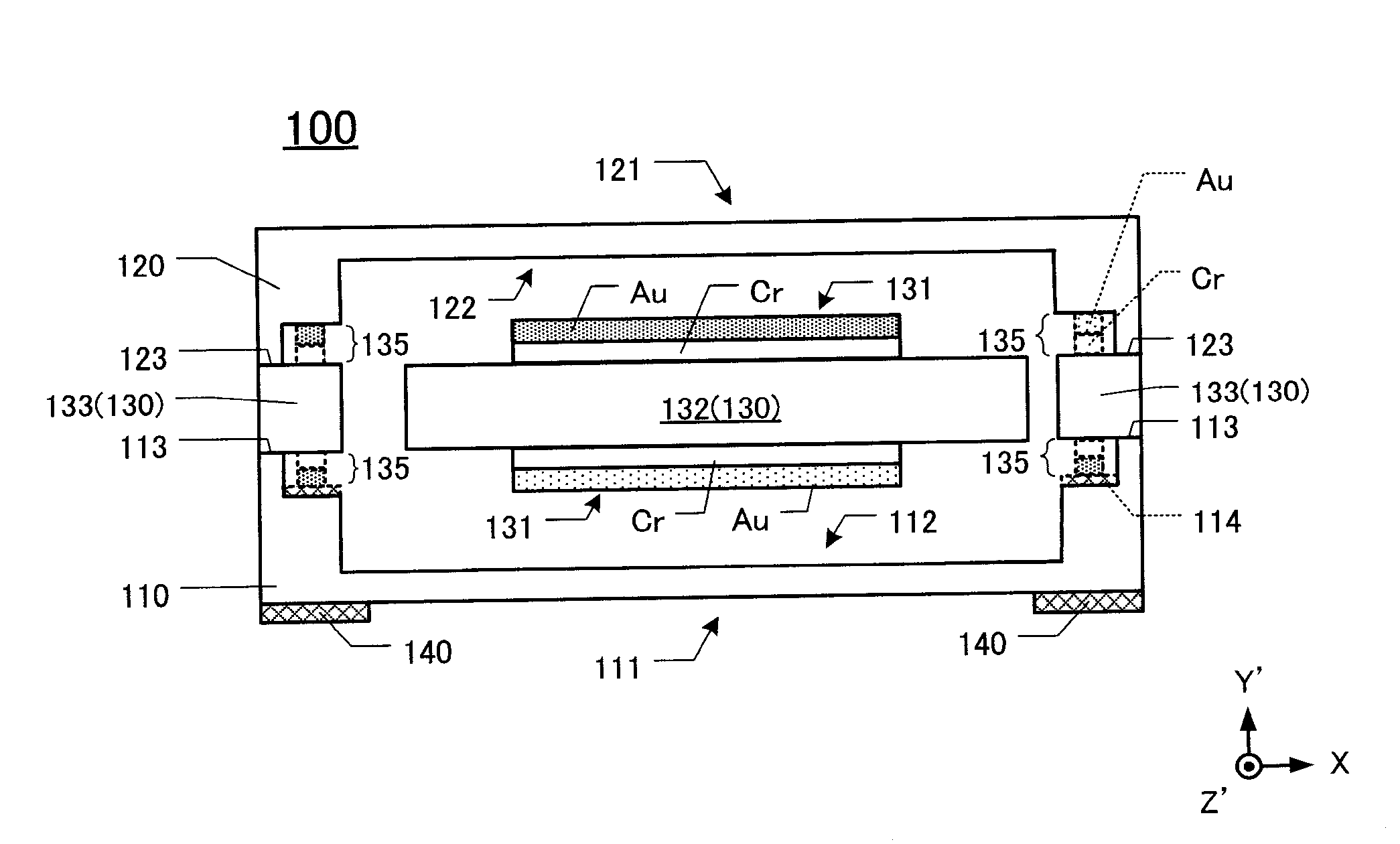
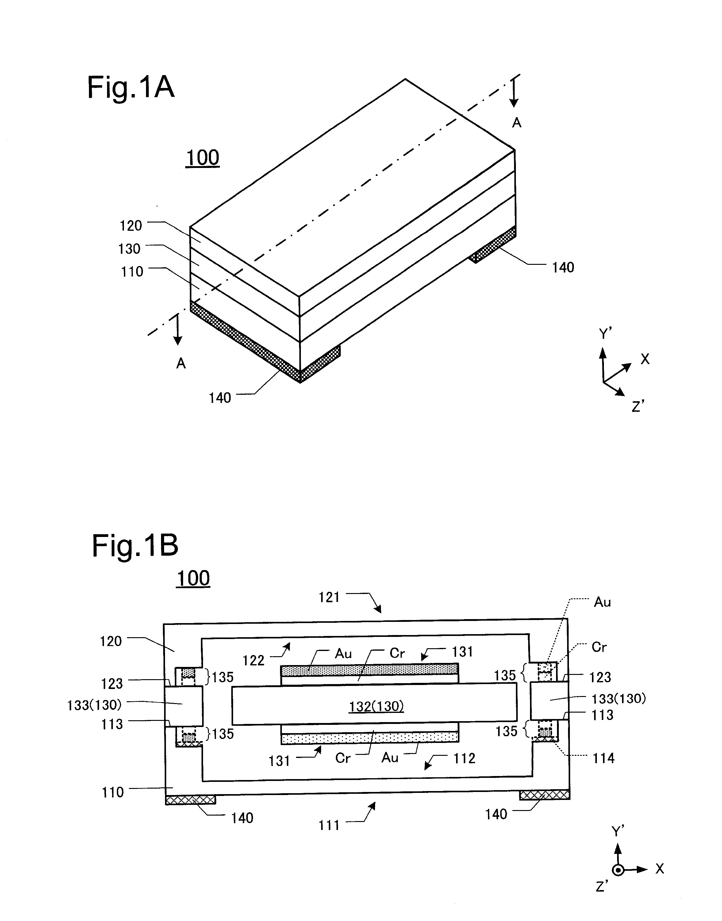
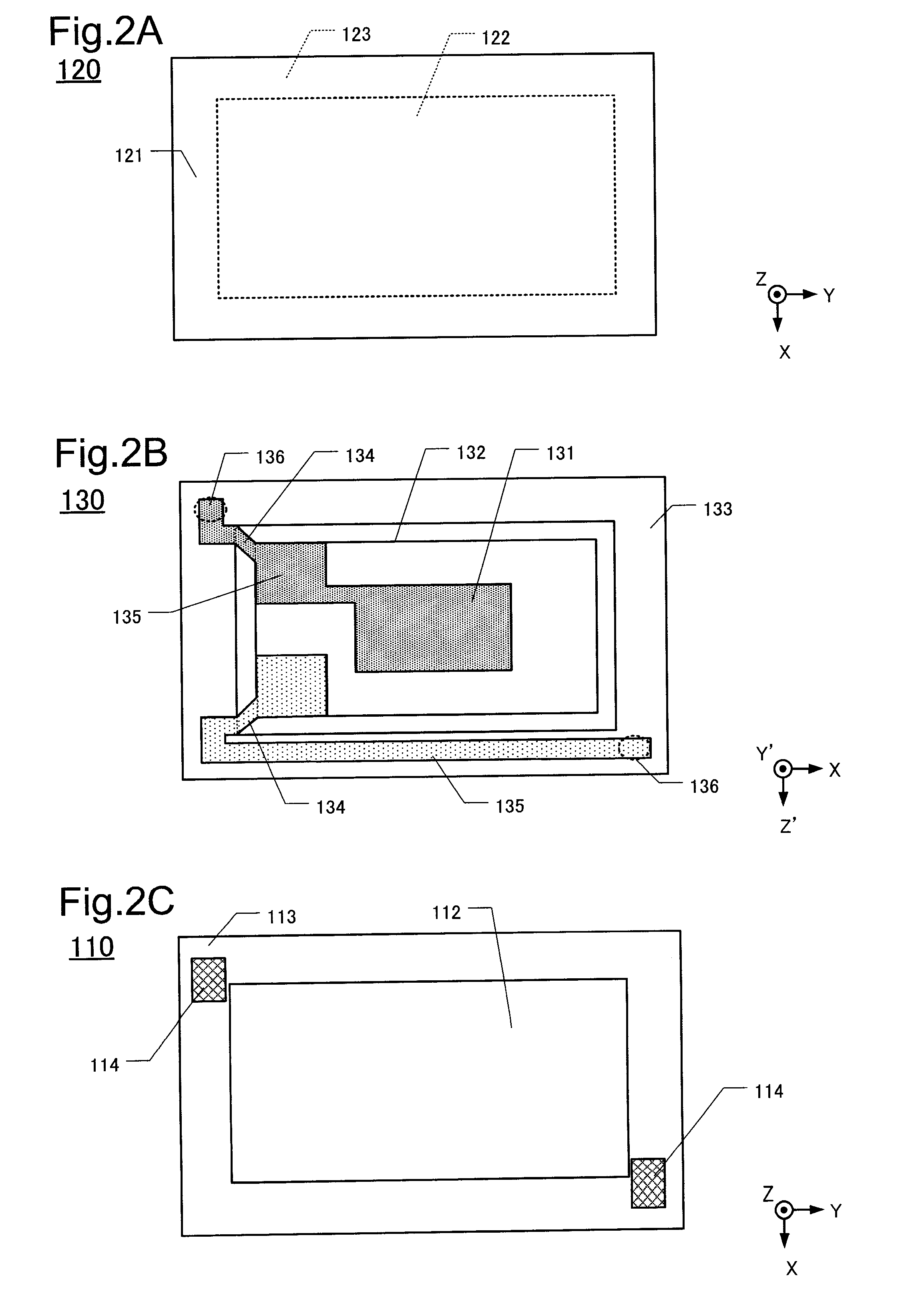
[0028]100> The quartz crystal device of this embodiment is a surface-mounting type quartz crystal device to be mounted on the surface of a printed circuit board by soldering. Hereinafter, the configuration of the quartz crystal device will be described with reference to FIG. 1 and FIG. 2. FIG. 1A is a perspective view of a quartz crystal device 100 and FIG. 1B is a sectional view taken along the line A-A of FIG. 1A. FIG. 2A is a plan view of a lid 120, FIG. 2B is a plan view of a quartz crystal element 130 and FIG. 2C is a plan view of a base 110.

[0029]As shown in FIG. 1A, the quartz crystal device 100 is constituted of the lid 120...


PUM

PropertyMeasurementUnit
temperatureaaaaaaaaaa
diameteraaaaaaaaaa
diameteraaaaaaaaaa

Abstract

The quartz crystal device of a first aspect comprises a quartz crystal element having an vibrating portion which vibrates when a voltage is applied and a frame portion which surrounds the periphery of the vibrating portion, the quartz crystal element being formed of an AT-cut quartz crystal material specified by the X-axis, the Y′-axis and the Z′-axis; a base which is bonded to one main surface of the frame portion, the base being formed of a Z-cut quartz crystal material specified by the X-axis, the Y-axis and the Z-axis; and a lid which is bonded to other main surface of the frame portion, the frame portion being formed of the Z-cut quartz crystal material. The Z′-axis of the quartz crystal element is coincident with the X-axis or the Y-axis of the base and the lid.

Description

CROSS-REFERENCE TO RELATED APPLICATION[0001]This application claims priority to and the benefit of Japan Patent Application No. 2010-077017 filed on Mar. 30, 2010 and Japan Patent Application No. 2011-029328 filed on Feb. 15, 2011 in the Japan Patent Office, the disclosure of which is incorporated herein by reference in its entirety.FIELD[0002]The present invention relates to a quartz crystal device using an AT-cut quartz substrate and a manufacturing method of the quartz crystal device.DESCRIPTION OF THE RELATED ART[0003]An AT-cut quartz crystal vibrating piece has been widely used as a reference source for the frequency and time in the vibrator of various types of electronic apparatuses. A surface-mounting type AT-cut quartz crystal vibrating piece is accommodated in a package made of ceramic or glass and the package is sealed off with a lid into a vacuum state or with inert gas filled therein. The AT-cut quartz crystal piece is affected by thermal changes because the coefficient ...

Claims


Application Information

Patent Timeline
Patent Type & Authority Applications(United States)
IPC IPC(8): H01L41/053H01L41/22H10N30/00H10N30/88H01L23/08H03H3/02H03H9/02
CPCH03H3/02H03H9/0595Y10T29/42H03H9/19H03H9/1021
Inventor TAKAHASHI, TAKEHIROMIZUSAWA, SYUICHI
Owner NIHON DEMPA KOGYO CO LTD
Learn More