
oscillator

a technology of oscillator and oscillator body, which is applied in the direction of generator stabilization and electric apparatus, can solve the problems that the apparatus cannot solve the above-described problem, and achieve the effects of reducing the influence, reducing the frequency variation due to temperature change, and high accuracy

Active Publication Date: 2015-01-29
NIHON DEMPA KOGYO CO LTD
View PDF2 Cites 14 Cited by
  • Summary
  • Abstract
  • Description
  • Claims
  • Application Information

AI Technical Summary

Benefits of technology

The patent describes an oscillator that can reduce the influence of temperature on the output of an electrical signal. This is achieved by using a differential signal between two oscillator circuits and alternately connecting them to either a computer or a signal path via a frequency reduction unit. The oscillator can also be designed to include parameters that can be set to reduce the variation in frequency caused by temperature change. The result is a simplified and accurate way to control the output of an oscillator signal.

Problems solved by technology

This apparatus, however, cannot solve the above-described problem.

Method used


Image

  • oscillator
  • oscillator
  • oscillator

Examples


Embodiment Construction

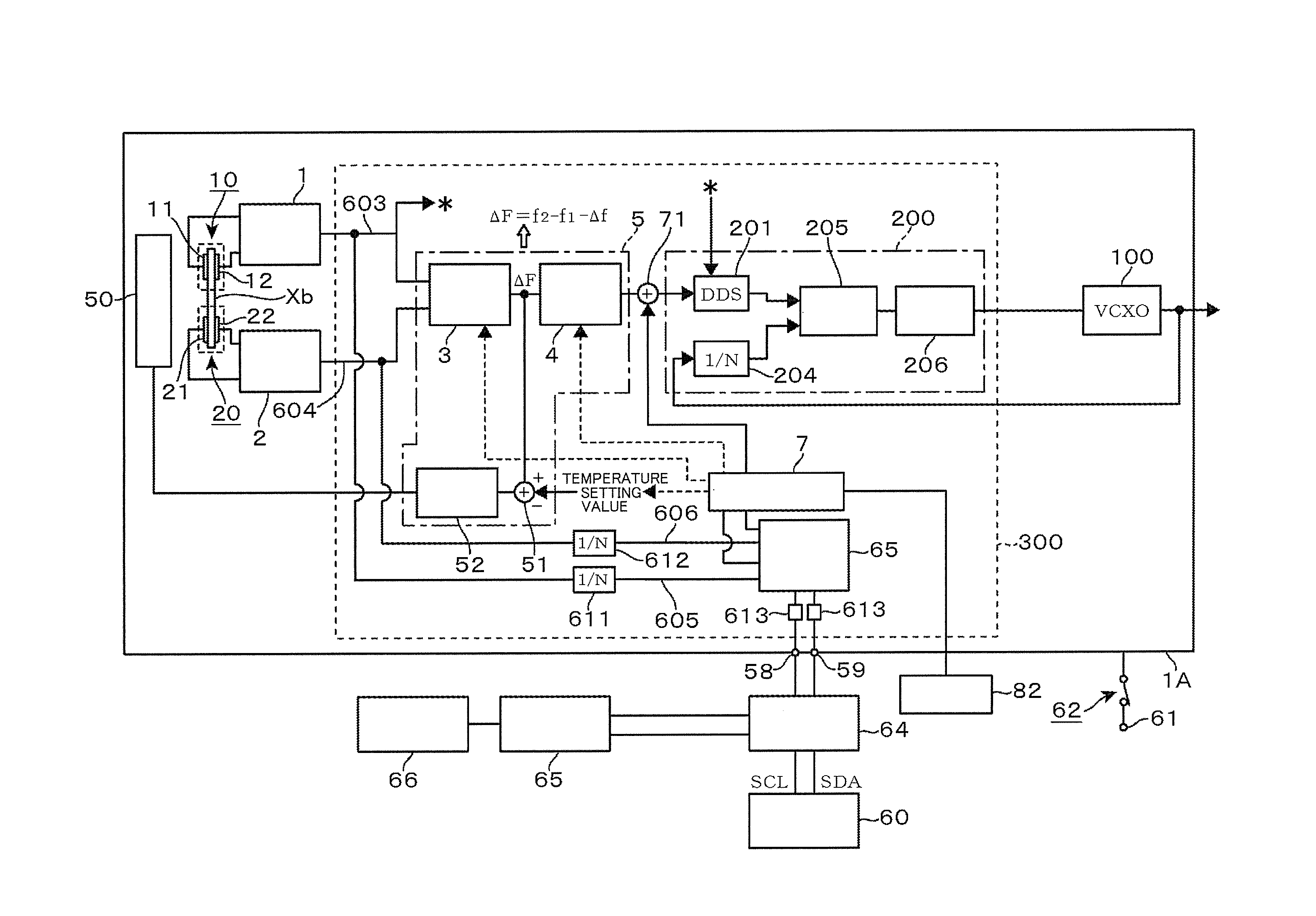
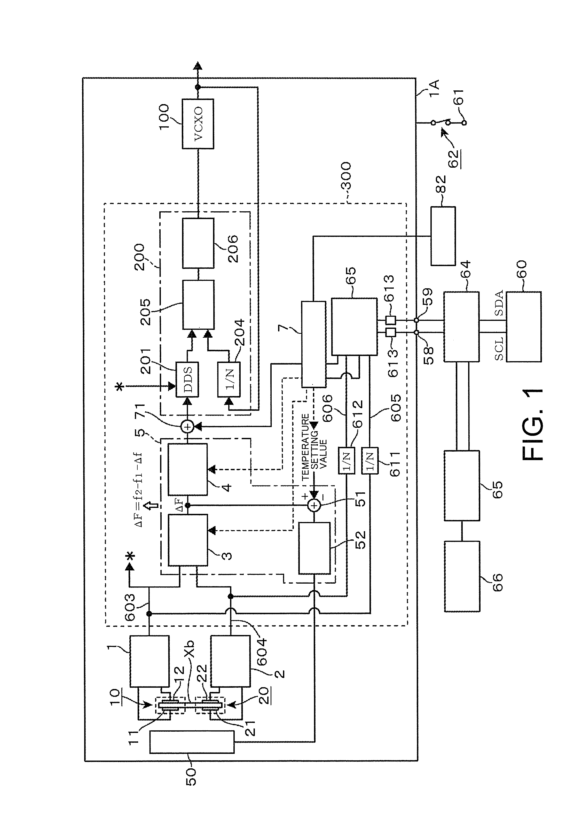
[0036]FIG. 1 is a block diagram illustrating an overall configuration of an oscillator 1A that uses a crystal oscillator according to an embodiment of this disclosure. The oscillator 1A is a frequency synthesizer that outputs a frequency signal having a setting frequency. The oscillator 1A includes a voltage controlled crystal oscillator 100, a control circuit unit 200, a crystal oscillator (reference numeral is not given), and a heater circuit 50. The voltage controlled crystal oscillator 100 includes a crystal unit. The control circuit unit 200 constitutes a Phase locked loop (PLL) in the voltage controlled crystal oscillator 100. The crystal oscillator generates a clock signal for operating a Direct Digital Synthesizer (DDS) circuit unit 201, which generates a reference signal of the PLL. The heater circuit 50 is a heat regulating unit that adjusts temperatures in an atmosphere, in which crystal units 10 and 20 in the crystal oscillator are placed. Accordingly, the above-describe...


PUM


Abstract

An oscillator uses a differential signal corresponding to a difference between an oscillation output f1 of a first oscillator circuit and an oscillation output f2 of a second oscillator circuit as a temperature detection value, and outputs a control signal for reducing an influence caused by a temperature characteristic of the oscillation output f1 based on the differential signal. The oscillator includes a switching unit configured to alternately switch between a first state where a first connecting terminal and a second connecting terminal are connected to a storage unit for access of an external computer to the storage unit, and a second state where the first connecting terminal and the second connecting terminal are respectively connected to a first signal path and a second signal path via a frequency reduction unit such that the output signals from the frequency reduction unit are extracted to an external frequency measuring unit.

Description

CROSS-REFERENCE TO RELATED APPLICATION[0001]This application claims the priority benefit of Japanese application serial no. 2013-156901, filed on Jul. 29, 2013. The entirety of the above-mentioned patent application is hereby incorporated by reference herein and made a part of this specification.BACKGROUND[0002]1. Technical Field[0003]This disclosure relates to an oscillator that uses, as a temperature detection value, a signal corresponding to a difference between an oscillation output f1 of a first oscillator circuit and an oscillation output f2 of a second oscillator circuit, and reduces an influence caused by temperature characteristics of the oscillation output f1.[0004]2. Description of the Related Art[0005]FIG. 18 illustrates a general constitution of a Temperature Compensated Crystal Oscillator (TCXO), which is an oscillator. Reference numeral 90 denotes a crystal unit, and reference numeral 91 denotes an oscillator circuit. Changing a control voltage, which is supplied from...

Claims


Application Information

Patent Timeline
Patent Type & Authority Applications(United States)
IPC IPC(8): H03L1/02
CPCH03L1/022H03L1/026
Inventor YORITA, TOMOYA
Owner NIHON DEMPA KOGYO CO LTD
Learn More