Efficient clocking scheme for ultra high-speed systems

a clocking scheme and ultra high-speed technology, applied in the direction of digital transmission, instruments, generating/distributing signals, etc., can solve the problems of affecting the efficiency of the system, the procedure of synchronizing the internal clock may take a relatively large amount of time, and the single clock signal is typically inadequate to accommodate all the devices, so as to reduce the required lock time, reduce the length of the delay line used, and increase the locking efficiency

Active Publication Date: 2008-11-18
MICRON TECH INC
View PDF6 Cites 3 Cited by
  • Summary
  • Abstract
  • Description
  • Claims
  • Application Information

AI Technical Summary

Benefits of technology

[0010]The present invention provides a system of reducing the required lock time for synchronous circuits by reducing the length of the delay line used in the synchronous circuit. The system generates three internal clock signals from an external clock signal. Each of the signals is separated by 1tCK or 2tCK depending on whether the external clock signal is divided by 3 or 6. One of the three signals is selected based on the timing of the three clock signals relative to a feedback signal. The selected signal is then used for feedback and synchronization purposes. Because the three clock signals are separated by 1tCK or 2tCK, the total length of the delay line can be reduced to a maximum of 1tCK or 2tCK as opposed to 3tCK or 6tCK if only one signal were used for synchronization purposes, thereby significantly increasing locking efficiency. Accordingly, the total lock time can be improved by as much as 66.67%. In another aspect of the invention, a method for improving the lock time comprises generating three internal clock signals and selecting one of the three signal based on timing characteristics relative to an external clock signal.

Problems solved by technology

Due to a variety of reasons, however, a single clock signal is typically inadequate to accommodate all the devices in complex circuits and computer systems.
Additionally, there may be issues associated with jitter performance and skewing of the clock signal when it is distributed at speeds approaching the several-gigahertz-range.
The procedure of synchronization of the internal clock may take a relatively large amount of time considering the speeds of today's devices and may bottle-neck the system.

Method used


Image

  • Efficient clocking scheme for ultra high-speed systems
  • Efficient clocking scheme for ultra high-speed systems
  • Efficient clocking scheme for ultra high-speed systems

Examples


Embodiment Construction

[0018]One or more specific embodiments of the present invention will be described below. In an effort to provide a concise description of these embodiments, not all features of an actual implementation are described in the specification. It should be appreciated that in the development of any such actual implementation, as in any engineering or design project, numerous implementation-specific decisions must be made to achieve the developers' specific goals, such as compliance with system-related and business-related constraints, which may vary from one implementation to another. Moreover, it should be appreciated that such a development effort might be complex and time consuming, but would nevertheless be a routine undertaking of design, fabrication, and manufacture for those of ordinary skill having the benefit of this disclosure.

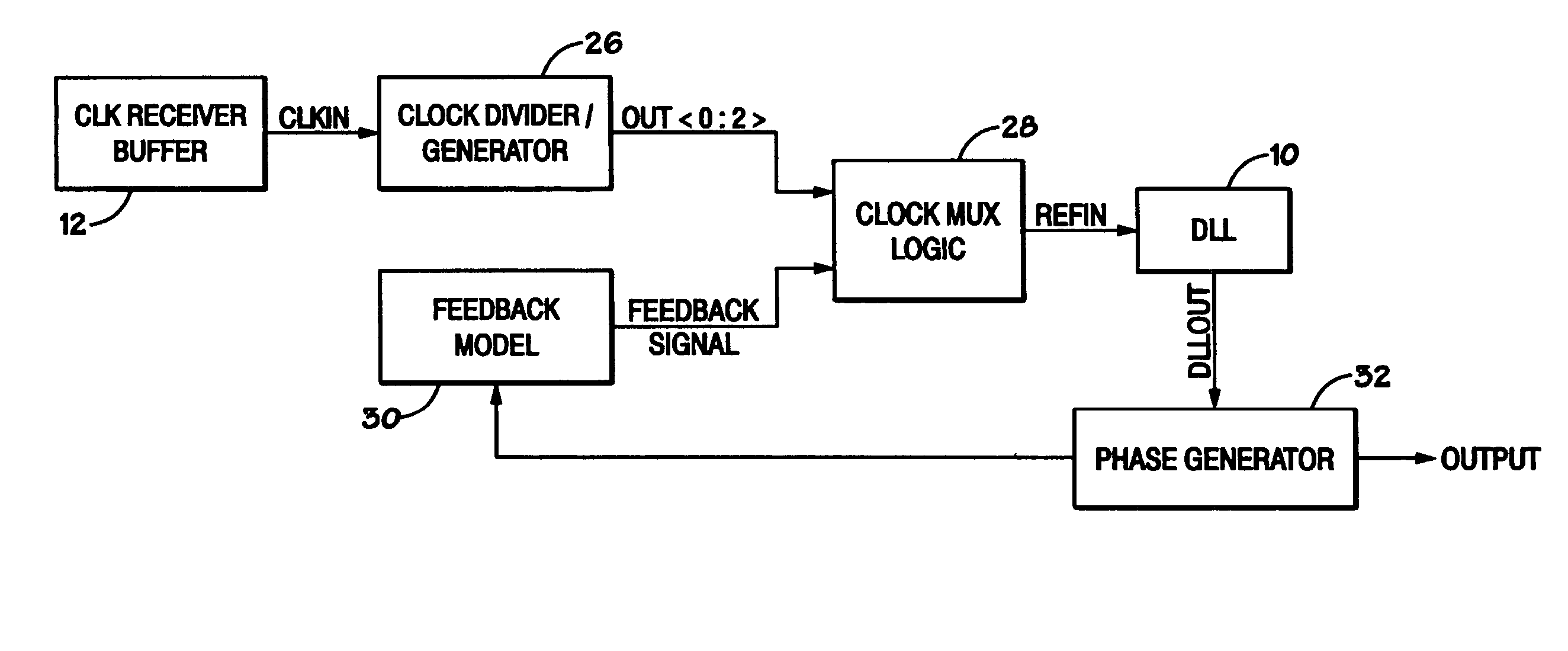
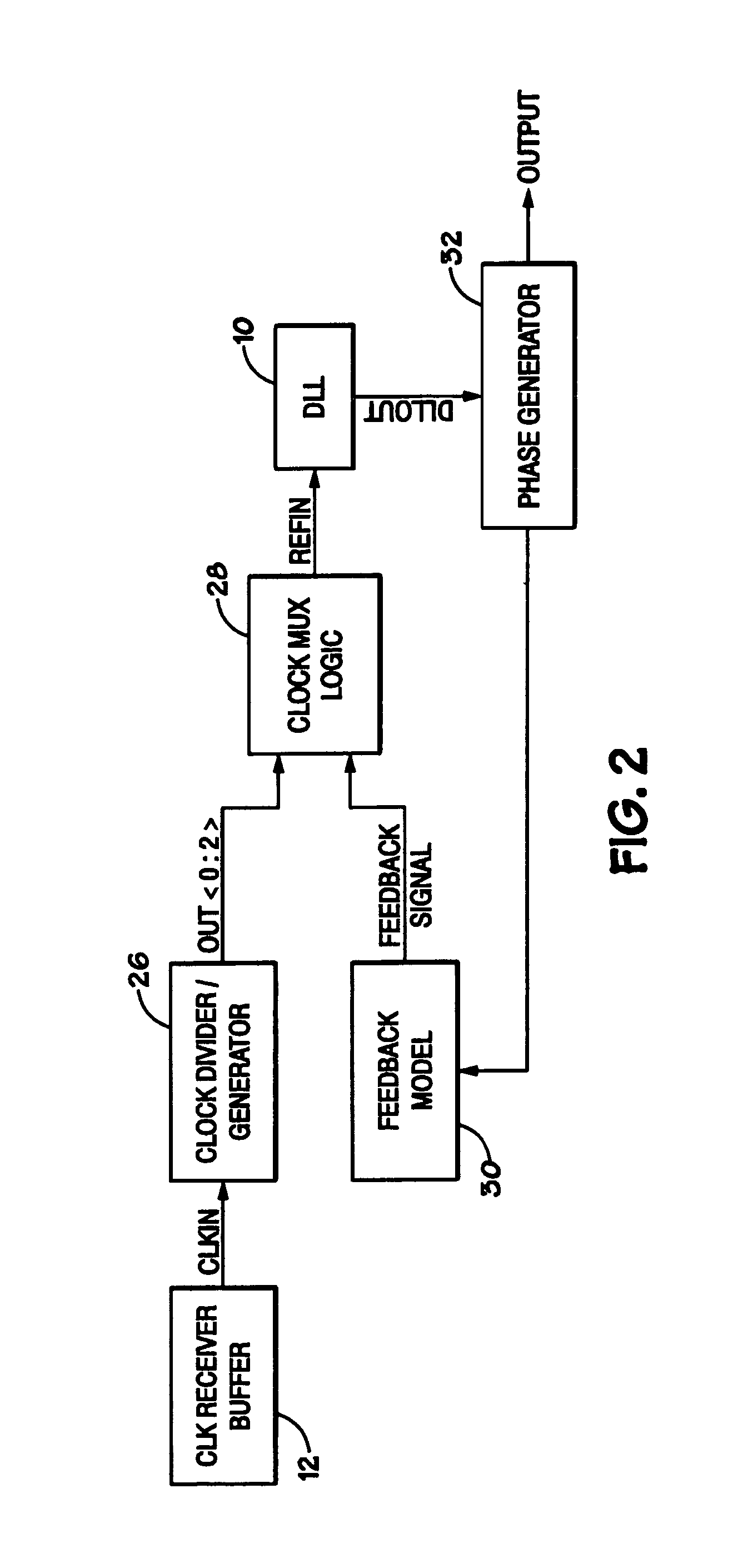
[0019]As described above, many issues arise when distributing a clock for synchronous devices and circuits, especially at high speeds. A common way to min...


PUM


Abstract

There is provided a system for comparing the phase characteristics of three generated clock signals, each having a unique phase relationship with an original clock signal, with the original clock signal and to select a signal based on the proximity of the phase characteristic of the three signals to the original signal. The selection of a clock signal that most closely approximates the original significantly reduces lock time when attempting to synchronize an internal clock with an external clock. Additionally, there is provided a method for comparing three clock signals with an original clock signal and selecting from the three clock signals one that is approximately in phase with the original clock signal.

Description

CROSS-REFERENCE TO RELATED APPLICATIONS[0001]The following commonly owned applications and patents are hereby incorporated by reference for all purposes:[0002]U.S. patent application Ser. No. 11 / 183,642, filed concurrently herewith, entitled “Methods and Apparatus for Dividing a Clock Signal,” by Feng Lin.BACKGROUND OF THE INVENTION[0003]1. Field of the Invention[0004]The present invention relates generally to the field of integrated circuits. More particularly, the invention relates to a fast and efficient system and method for selecting a single internal clock signal from multiple internal clock signals to synchronize with an external clock signal.[0005]2. Description of the Related Art[0006]This section is intended to introduce the reader to various aspects of art that may be related to various aspects of the present invention, which are described and / or claimed below. This discussion is believed to be helpful in providing the reader with background information to facilitate a be...

Claims


Application Information

Patent Timeline
Patent Type & Authority Patents(United States)
IPC IPC(8): G06F1/00G06F1/04G06F1/12
CPCG06F1/04G11C7/22G11C7/222G11C11/4076G11C29/02G11C29/023H03L7/0814H03L7/0816
Inventor LIN, FENG
Owner MICRON TECH INC
Why Eureka
Try Eureka