
Tape feeder for component mounter providing stable tape feeding

a technology of component mounters and feeders, which is applied in the field of feeders for chip mounters, can solve the problems of fine components being turned, susceptible to foreign matter contamination of integrated circuit chips b>5/b>, and assuming wrong postures, etc., and achieves the effect of improving work efficiency

Active Publication Date: 2008-11-11
HANWHA AEROSPACE CO LTD
View PDF3 Cites 8 Cited by
  • Summary
  • Abstract
  • Description
  • Claims
  • Application Information

AI Technical Summary

Benefits of technology

[0014]The present invention provides a tape feeder for use in chip mounters that can improve work efficiency and prevent chips from assuming wrong postures, and a chip mounting method therefor.
[0016]Hence, without substantially increasing the time required to feed a carrier tape, an impact generated at ends of the teeth of the sprocket during the feeding of the carrier tape can be reduced. Due to the reduction of the impact, fine components are prevented from being conventionally turned over or assuming wrong postures. This leads to a stable supply of components to a component mounter.

Problems solved by technology

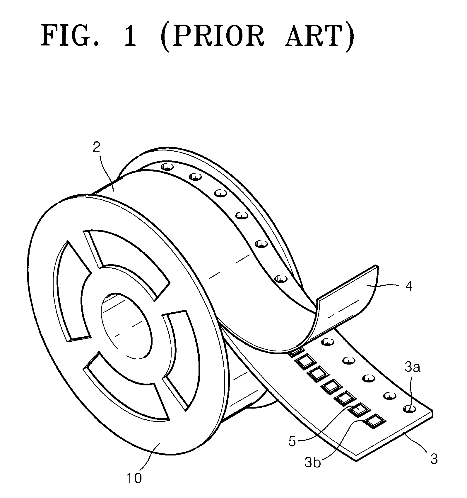
Products such as integrated circuit (IC) chips 5 are susceptible to contamination by foreign matters, such as dust, for example.
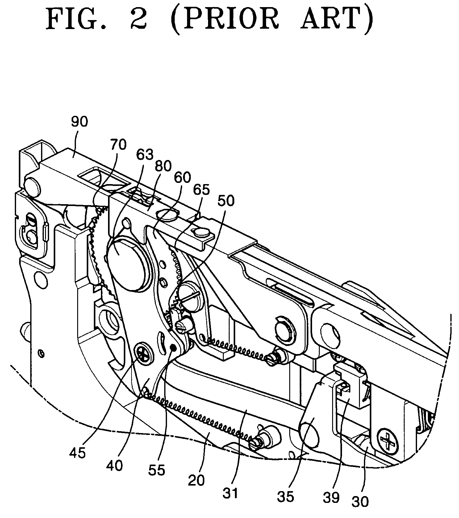
The impact causes fine components to be turned over or causes them to assume wrong postures prior to being picked up.
Until now, to solve these problems the overall speed of feeding fine components has been decelerated, affecting the whole feeding and mounting process.
Disadvantageously, overall deceleration of feeding components causes low work efficiency.

Method used


Image

  • Tape feeder for component mounter providing stable tape feeding
  • Tape feeder for component mounter providing stable tape feeding
  • Tape feeder for component mounter providing stable tape feeding

Examples


Embodiment Construction

[0031]FIGS. 3A and 3B are perspective views of an embodiment of a tape feeder for use in chip mounters, according to an aspect of the present invention. A carrier tape feeding unit is installed in a front part of the tape feeder. The carrier tape feeding unit feeds a carrier tape 2 (FIG. 1), which accommodates chips 5, at intervals of a predetermined pitch.

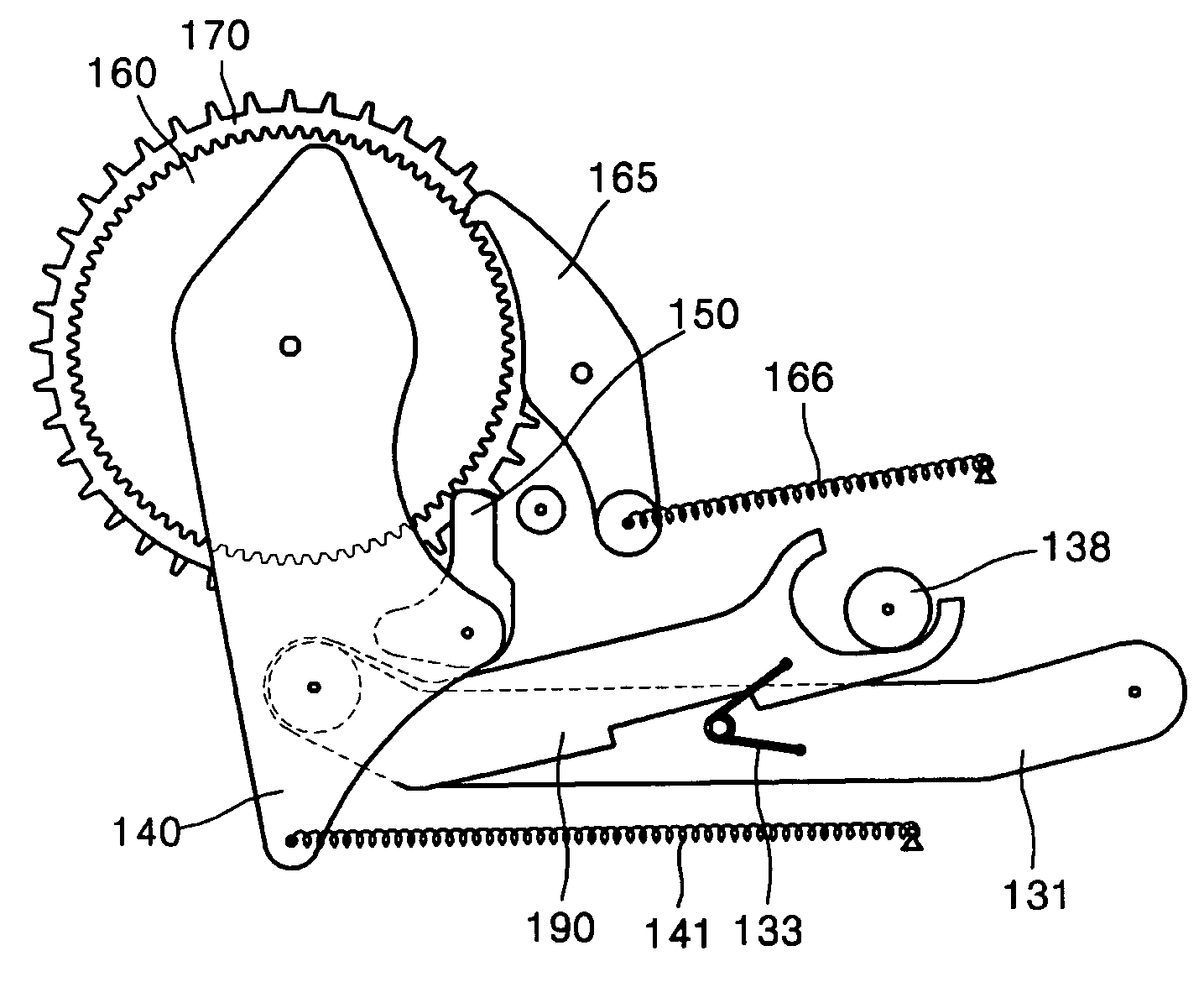
[0032]FIG. 4 is an enlarged perspective view of the carrier tape feeding unit included in the tape feeder illustrated in FIGS. 3A and 3B. FIG. 5A is a schematic plan view of the carrier tape feeding unit illustrated in FIG. 4. The carrier tape feeding unit includes a frame 120, a ratchet gear 160, a sprocket 170, a pawl 150, a pivot lever 140, a first link 131, a second link 190, a contact unit including a bearing shaft 137 and a bearing 138, a torsion spring 133, a reverse rotation preventing unit 165, and a position detection unit 139.

[0033]The function and operation of the carrier tape feeding unit will now be described. Referr...


PUM

PropertyMeasurementUnit
velocityaaaaaaaaaa
normal rotationaaaaaaaaaa
reverse rotation preventingaaaaaaaaaa

Abstract

Provided are a tape feeder for use in chip mounters that can reduce a chip feeding duration and prevent chips from being turned over or assuming wrong postures to feed the chips stably, and a chip mounting method. The tape feeder includes a second link having one end linked to a link shaft through which a first link and a pivot lever are combined and the other end in which a slot curved at a predetermined inclination is formed. The velocity at which a carrier tape is fed changes according to the inclination of the curve of the slot with respect to the moving direction of the first link, the curve contacting the contact unit upon the movement of the first link in a direction helping to rotate a ratchet gear.

Description

CROSS-REFERENCE TO RELATED PATENT APPLICATIONS[0001]This application claims the benefit of Korean Patent Application No. 10-2005-0094521, filed on Oct. 7, 2005, in the Korean Intellectual Property Office, the disclosure of which is incorporated herein in its entirety by reference.BACKGROUND OF THE INVENTION[0002]1. Field of the Invention[0003]The present invention relates generally to a tape feeder for use in chip mounters, and more particularly, to a tape feeder for use in chip mounters that includes a carrier tape feeding unit for stably feeding chips, and a chip mounting method therefor.[0004]2. Description of the Related Art[0005]Chip mounters are automated apparatuses used to mount a component, such as, a semiconductor chip, on a predetermined location on a printed circuit board (PCB).[0006]Products such as integrated circuit (IC) chips 5 are susceptible to contamination by foreign matters, such as dust, for example. Hence, to be protected from foreign matters and easily handle...

Claims


Application Information

Patent Timeline
Patent Type & Authority Patents(United States)
IPC IPC(8): H05K13/02
CPCH05K13/021Y10T29/4913Y10T29/49133Y10T29/49131Y10T29/53465Y10T29/49144Y10T29/53191Y10T29/53261Y10T29/53178Y10T29/53174H05K13/0419B65H35/06
Inventor CHOI, HYUNG-SOOLEE, TAE-YOUNG
Owner HANWHA AEROSPACE CO LTD
Learn More