
Scroll type fluid machine having a first scroll wrap unit with a scroll member and a scroll receiving member, and a second scroll wrap unit engaged with the first scroll wrap unit

a fluid machine and scroll technology, applied in the direction of liquid fuel engines, machines/engines, rotary piston liquid engines, etc., can solve the problems of large load on bearings, parts without contributing to compression, and parts that cannot be discharged, etc., to achieve high speed rotation, increase discharge quantity, and enough strength

Active Publication Date: 2008-11-04
SCROLL GIKEN
View PDF8 Cites 10 Cited by
  • Summary
  • Abstract
  • Description
  • Claims
  • Application Information

AI Technical Summary

Benefits of technology

[0009]Thus, the present invention provides a scroll type fluid machine in which wrap's a strength may be increased, rotation balance may be increased and useless spaces between the wraps may be removed.
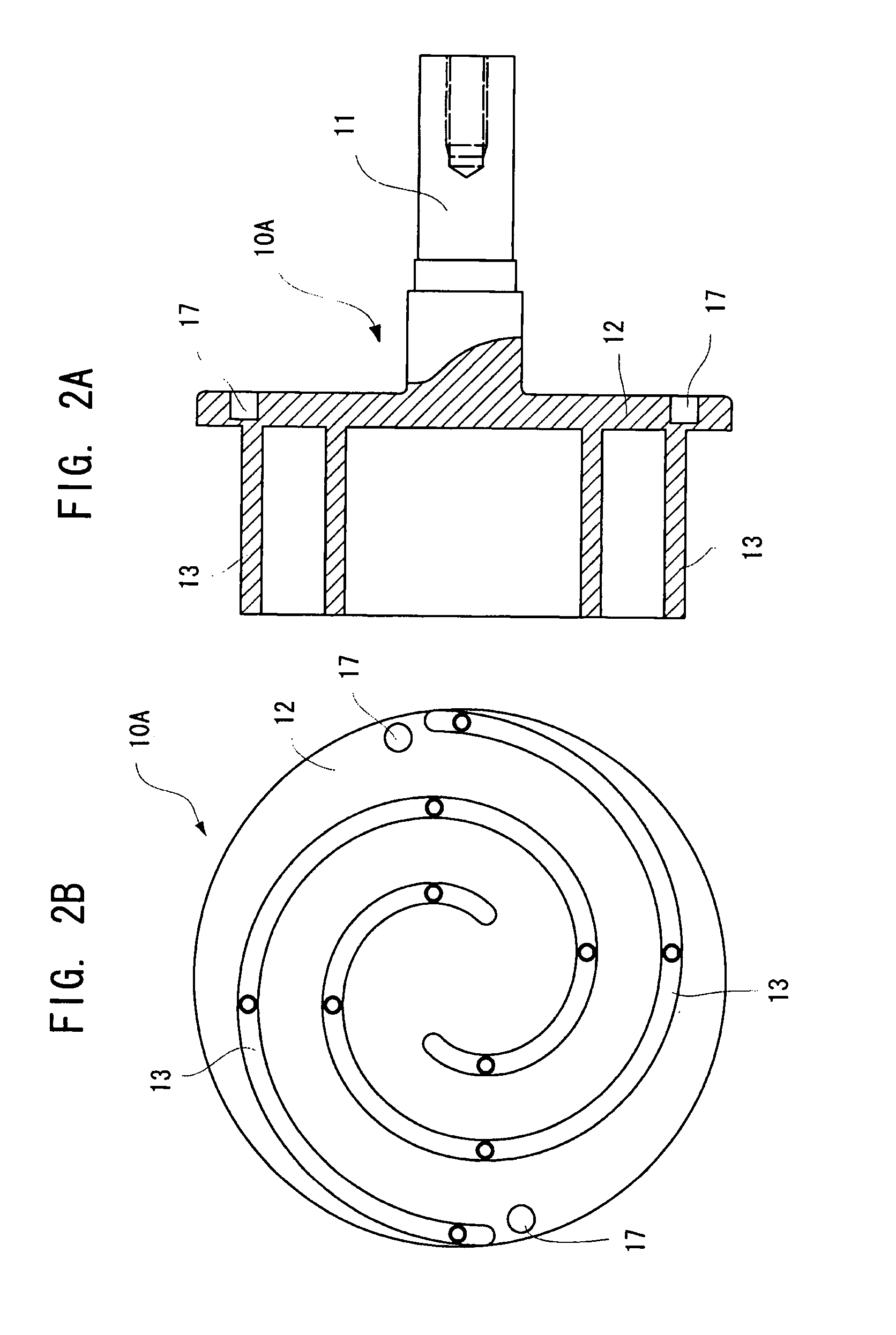
[0014]Thus, in this invention, because the both ends of every wrap of the second wrap group in the second scroll unit are held by the ring portion being on the radial outside and the connection block portion being on the radial inside, so that enough strength is achieved, and further because the second scroll unit is balanced well to a rotation center of the laps, high speed rotation is possible.
[0015]Furthermore, since the wraps of the first wrap group are inserted into the insertion spaces defined by the wraps of the second wrap group and since an outer peripheral end Φend of every wrap of the second wrap group is extended to an outer peripheral end Φend of every wrap of the first wrap group, the compression spaces constituted of the first wrap group and the second wrap group can work effectively in outer peripheral walls of outer peripheral ends Φend of the wraps of the first wrap group, so that it is possible to increase a quantity of discharge.
[0016]According to the present invention, since rotation balance is good, high speed rotation is possible, and enough quantity of discharge can be obtained, pulsation of discharge fluid can be prevented and it can be possible to correspond to change of discharged quantity quickly.

Problems solved by technology

However, because thrust load acts on the end plates in a direction pushing the end plates away from each other, there is a disadvantage in that a large load is applied to bearings.
Besides, in the case that a volume of the closed space is increased in order to increase discharge volume, the scroll wraps have to be elevated, but in this case, since radial load is applied perpendicularly to an axis at a middle position of the wrap's height, a disadvantage arises in that an upsetting moment is increased in the case of the cantilever type arrangement as shown in JP 09-133087.
A scroll type fluid machine disclosed in the monograph is that: because two wraps with the same shape are used in a drive scroll side and a follower scroll side respectively and they are combined so that they are deviated by π / 2 (90°), their end portions are deviated by π / 2 (90°), so that there is a disadvantage such that parts without contributing to compression are arisen.

Method used


Image

  • Scroll type fluid machine having a first scroll wrap unit with a scroll member and a scroll receiving member, and a second scroll wrap unit engaged with the first scroll wrap unit
  • Scroll type fluid machine having a first scroll wrap unit with a scroll member and a scroll receiving member, and a second scroll wrap unit engaged with the first scroll wrap unit
  • Scroll type fluid machine having a first scroll wrap unit with a scroll member and a scroll receiving member, and a second scroll wrap unit engaged with the first scroll wrap unit

Examples


Embodiment Construction

[0022]Hereinafter, an embodiment of the present invention is explained with reference to the drawings.

[0023]A scroll type scroll machine 1 according to the present invention comprises, for instance as shown in FIG. 1, at least a housing 3 fixed on a base 2, a first scroll unit (a drive scroll unit in this embodiment) 10 held rotatably on the housing 3 and a second scroll unit (a follower scroll unit in this embodiment) 20 grasped slidably by the drive scroll unit 10 and performing a gyrating movement relative to the drive scroll unit 10 by a rotation synchronous mechanism 30, in which volumes of compression spaces 40 defined by the drive scroll unit 10 and the follower scroll unit 20 are reduced from the outer peripheral side to the center side in turn in order to perform a compression action.

[0024]The housing 3 is constituted of a first cylindrical housing 3A, a second housing 3B and a third housing 3C which close both axial ends of the first housing 3A, wherein the second housing ...


PUM


Abstract

A scroll type fluid machine includes a housing, a first scroll unit arranged rotatably in the housing and a second scroll unit rotating with rotation of the first scroll unit and gyrating relative to the first scroll unit to vary volumes of compression spaces. The first scroll unit includes a first wrap group including two end plates with support shafts supported rotatably by the housing and scrolled wraps arranged uniformly. The second scroll unit includes a cylindrical outer peripheral ring portion held slidably between the end plates of the first scroll unit, a connection block portion located in a center portion and a second wrap group having plural scrolled wraps extending from the ring portion to the connection block portion to define insertion spaces into which the wraps of the first wrap group are inserted and, with the first wrap group, forming compression spaces.

Description

BACKGROUND OF THE INVENTION[0001]This invention relates to a scroll type fluid machine comprising a first scroll and a second scroll which performs a gyrating movement relative to the first scroll relatively.[0002]JP 09-133087 A discloses a whole system rotation scroll type fluid machine in which scrolled wraps extend from a drive scroll end plate and a follower scroll end plate, respectively, and are engaged with each other. A drive scroll is gyrated relative to a follower scroll to make closed spaces formed by rotation of the both scrolls move from a peripheral side to an inner side so as to reduce volume of the closed spaces, and in which sucked fluid is compressed and discharged.[0003]JP2004-286025 A by this inventor discloses a scroll type fluid machine which comprises a casing; a follower scroll unit which is constituted of at least an outer peripheral block held on the casing rotatably and a follower wrap extending spirally from the outer peripheral block inwardly; a drive sc...

Claims


Application Information

Patent Timeline
Patent Type & Authority Patents(United States)
IPC IPC(8): F03C2/00F03C4/00F04C2/00
CPCF04C18/02F04C18/0246
Inventor KAWAZOE, SHINJI
Owner SCROLL GIKEN
Learn More