Method and device for melting glass using an induction-heated crucible with cooled crust

a technology of induction heating and crucible, which is applied in the direction of glass shaping apparatus, lighting and heating apparatus, furnace components, etc., can solve the problem of not being able to connect the melting crucible to the downstream further processing unit using conventional components, and achieve the effect of boosting the circulation of the entire mel

Inactive Publication Date: 2008-11-04
SCHOTT AG
View PDF17 Cites 5 Cited by
  • Summary
  • Abstract
  • Description
  • Claims
  • Application Information

AI Technical Summary

Benefits of technology

[0012]It is an object of the invention to refine a melting method or apparatus of the known type in such a way that simple components which are as conventional as possible are used to link the melting unit to the further-processing stations and that the glass quality is not adversely affected by the forced use of a connecting technique in accordance with the prior art.
[0015]According to the invention, the glass level in the crucible projects above the upper end of the coil arrangement at least sufficiently far for it to be possible for the glass outlet to be arranged completely above the coil arrangement. Furthermore, the outer end of the glass outlet projects beyond the outer radius of the induction coil. This means that the glass can be fed for further processing without flowing through the coil region. It is simple and inexpensive to connect the melting crucible to the next further-processing unit using conventional components, since there are no disruptive coils in the way. There are no restrictions whatsoever on the choice of subsequent components, and consequently any possible adverse effects on the quality of the glass resulting from the type of connection can be minimized when a suitable connection technique is selected.
[0017]It has been found that this effect can be boosted still further by the use of the cooled bridge. Melt which passes into the region of the cooled bridge is cooled by the latter and drops downward toward the base. A downward flow is formed, and this evidently generates a type of “cooling curtain” or “flow curtain” in the melt. This behavior likewise boosts the circulation of the entire melt located in the melting region of the crucible. The use of bridges in melting technology is inherently known, and these bridges are usually employed in order to prevent undissolved constituents of the batch from flowing through direct to the glass outlet. In addition to its purely mechanical separating action between melting region and outlet region, the water-cooled bridge according to the invention therefore also provides a thermal separation between the two regions by the formation of the above-described “cooling curtain” or “flow curtain”. Consequently, the separating action of the bridge extends much further into the glass volume than its simple geometric dimensions.

Problems solved by technology

Surprisingly, it has emerged that for uniform melting of the contents of the crucible it is not absolutely imperative for the entire volume of the melt to be arranged inside the induction coil, as is known from the prior art, a measure which in the prior art is supposed to result in the high-frequency energy being introduced as uniformly as possible in the entire volume of the melt but on the other hand means that it is not possible for the melting crucible to be connected to the downstream further-processing units using conventional components, on account of the disruption caused by the coil arrangement.

Method used


Image

  • Method and device for melting glass using an induction-heated crucible with cooled crust
  • Method and device for melting glass using an induction-heated crucible with cooled crust
  • Method and device for melting glass using an induction-heated crucible with cooled crust

Examples


Embodiment Construction

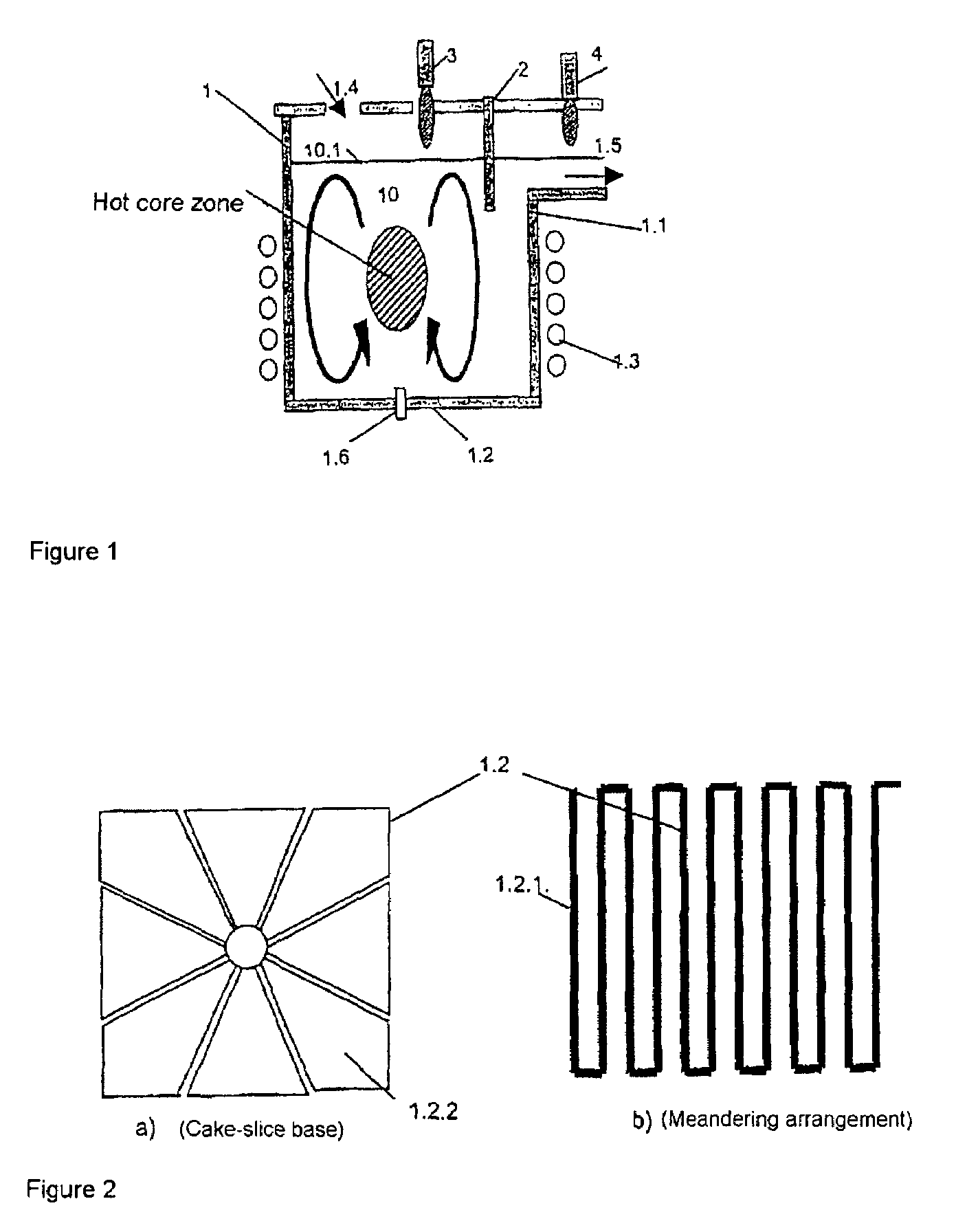
[0028]FIG. 1 shows a melting apparatus in accordance with the invention, having a skull crucible 1. In the embodiment illustrated, the skull crucible 1 comprises a cylindrical crucible wall 1.1.

[0029]Details of the crucible structure are described below but are not all illustrated in the figure, for the sake of clarity.

[0030]The crucible wall 1.1 is constructed from a ring of vertical metal tubes which are connected to one another at the top and bottom in meandering form. The crucible base 1.2 may likewise comprise metal tubes or segments, or may alternatively be made from refractory material.

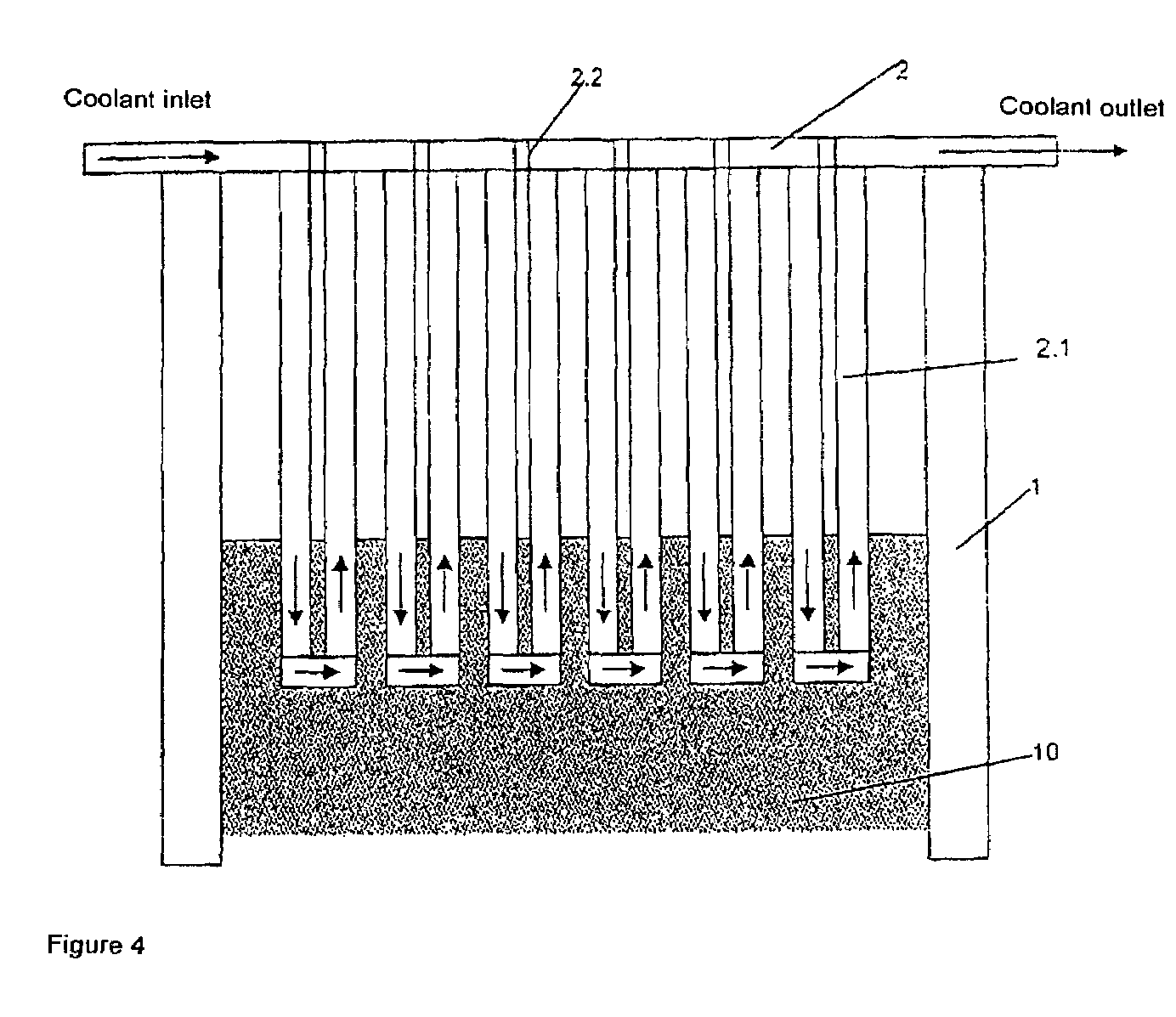
[0031]The metal tubes are connected to at least one coolant feed and coolant discharge. The coolant used is generally water. The coolant is guided over a meandering path corresponding to the arrangement of the metal tubes. Depending on the size of the crucible, it is possible to provide a plurality of coolant circuits for cooling individual ring segments. In the base region of the crucible, in ...


PUM

PropertyMeasurementUnit
volumeaaaaaaaaaa
volumeaaaaaaaaaa
depthaaaaaaaaaa

Abstract

A method and an apparatus for the rapid melting of glasses in a skull crucible is provided. The method and apparatus introduce high-frequency energy into the contents of the crucible by means of a coil arrangement surrounding the skull crucible, in order to heat the melt, and the batch is laid and the molten glass discharged in the upper region of the crucible, and undissolved constituents of the batch are retained by means of a cooled bridge which is immersed in the melt. The glass is taken off above the coil arrangement and is fed for further processing without flowing through the coil region.

Description

[0001]This application is a 371 of PCT / EP02 / 11006 filed on 1 Oct. 2002.BACKGROUND OF THE INVENTION[0002]1. Field of the Invention[0003]The invention relates to a method and an apparatus for the rapid melting of in particular high-purity, aggressive and high-melting glasses in a skull crucible, in which high-frequency energy is introduced into the contents of the crucible by means of a coil arrangement surrounding the skull crucible, in order to heat the melt, and the batch is laid and the molten glass discharged in the upper region of the crucible, and undissolved constituents of the batch are retained by means of a cooled bridge which is at least partially immersed in the melt from above.[0004]2. Description of Related Art[0005]Nowadays, aggressive glasses which are required to have a high purity are melted discontinuously in platinum crucibles or continuously in platinum tank furnaces. Both the melting tank furnace and the refining tank furnace and the homogenization tank furnace ...

Claims


Application Information

Patent Timeline
Patent Type & Authority Patents(United States)
IPC IPC(8): C03B5/02C03B1/02H05B6/24C03B3/00C03B5/18C03B5/187C03B5/193C03B5/235F27D11/06H05B6/34H05B6/36
CPCC03B1/02C03B3/00C03B5/021C03B5/18C03B5/187C03B5/193C03B2211/70C03B2211/71Y02P40/57
Inventor ROMER, HILDEGARDLEISTER, MICHAELKOLBERG, UWEMENNEMANN, KARLRAKE, GUIDOSCHAFER, ERNEST WALTERNUTTGENS, SYBILLOHMSTEDE, VOLKER
Owner SCHOTT AG
Why Eureka
Try Eureka