
Linearizer circuit

a linearizer and circuit technology, applied in the direction of electric variable regulation, speed/acceleration/shock measurement device testing/calibration, instruments, etc., can solve the problems of circuit design, nonlinearity of typical capacitive pressure sensors, and hardly being practicabl

Inactive Publication Date: 2008-10-28
MICRO ANALOG SYST
View PDF5 Cites 6 Cited by
  • Summary
  • Abstract
  • Description
  • Claims
  • Application Information

AI Technical Summary

Benefits of technology

[0006]An object of the present invention is thus to provide a feasible linearizer circuit for correcting nonlinearity of a capacitive pressure sensor.
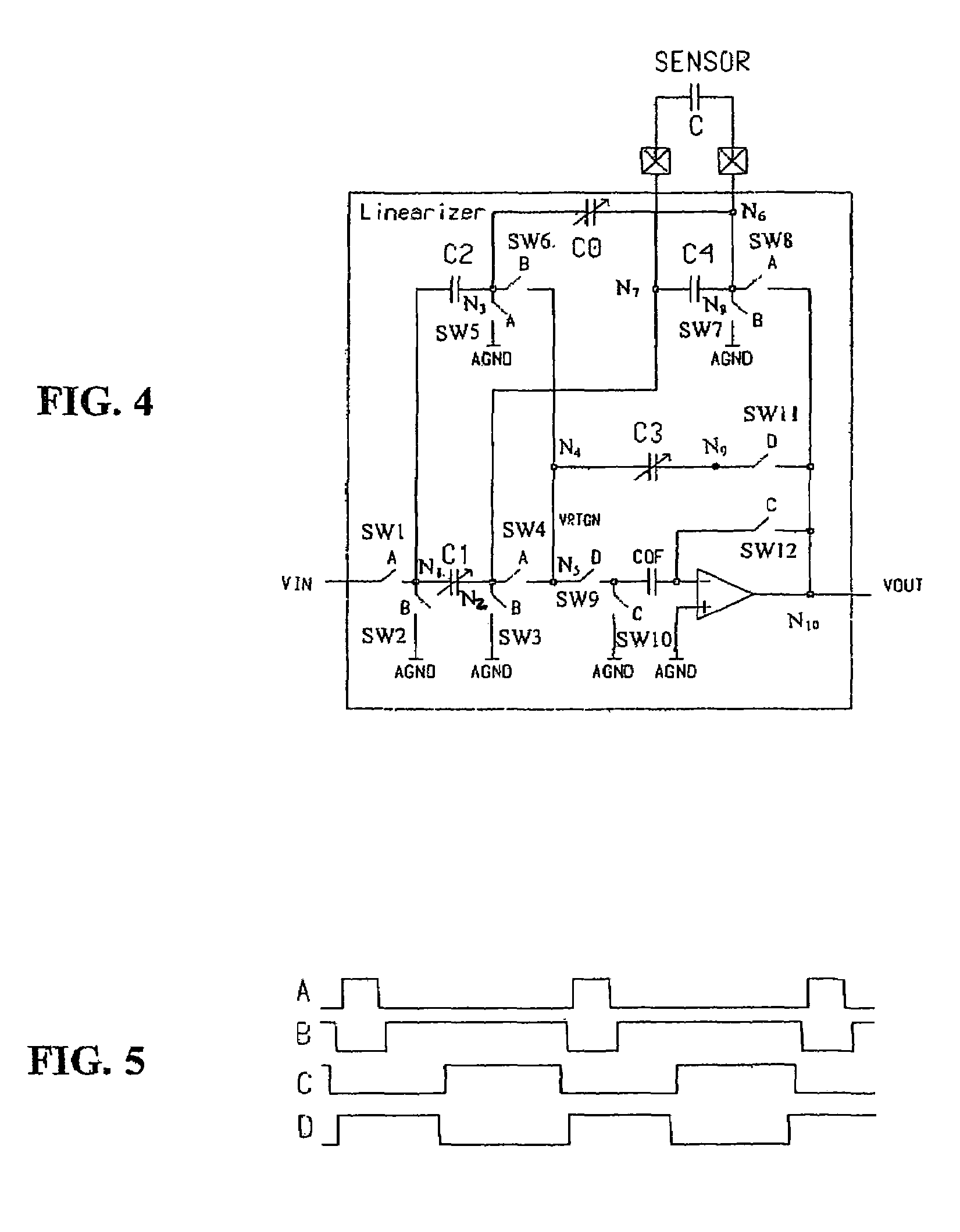
[0008]The present invention is based on an operational amplifier configuration comprising a feedback network of switched capacitor type, clock means for controlling the feedback network of switched capacitor type between a first switching phase and a second switching phase. In such a switched capacitor configuration, dc gain of the operational amplifier configuration in the second switching mode can be adapted to realize a linearization function required to substantially linearize a non-linear capacitance-pressure characteristic of a capacitive pressure sensor when the capacitive pressure sensor is connected to be part of the feedback network. Capacitor values required for capacitance value C of the capacitive pressure sensor can be calculated easily. In an embodiment of the invention, the feedback network of switched capacitor type includes adjustable capacitors for adapting the linearizer circuit to parametric variations among different capacitive pressure sensors. In the circuit configuration according to the present invention, the switched capacitor technique offers a way to implement the required linearizing function for a capacitive pressure sensor with a simple circuit. It also easily realizes a capacitance-to-voltage conversion necessary with a capacitive sensor.

Problems solved by technology

A typical capacitive pressure sensor is highly nonlinear.
The solution of p from Equation 1 leads to a complex expression involving square root, hardly being feasible from the point of view of circuit design.
In any case, a complicated electronic circuitry is required.
Even if the capacitance-pressure relation were approximated by an equation simpler than Equation 1, it would still be difficult to design an electronic circuit which outputs signal p(C) when sensor capacitance is C.

Method used


Image

  • Linearizer circuit
  • Linearizer circuit
  • Linearizer circuit

Examples


Embodiment Construction

[0016]For purposes of describing the exemplary embodiments, the right-hand side expression in Equation 1 can be accurately approximated by a simpler one:

[0017]C⁡(p)=C00+C0⁢p0p0-p,(2)

[0018]where C00, C0 and p0 are fitting parameters. Then, solving p from Equation 2, we have

[0019]p⁡(C)=p0⁡(1-C0C-C00)=p0⁢C-C00-C0C-C00=C-C00-C0Cp0-C00p0.(3)

[0020]Equation 3 gives a function necessary for linearizing a capacitive pressure sensor. In the following, examples of linearizer circuits of the invention realizing the function of Equation 3 are described.

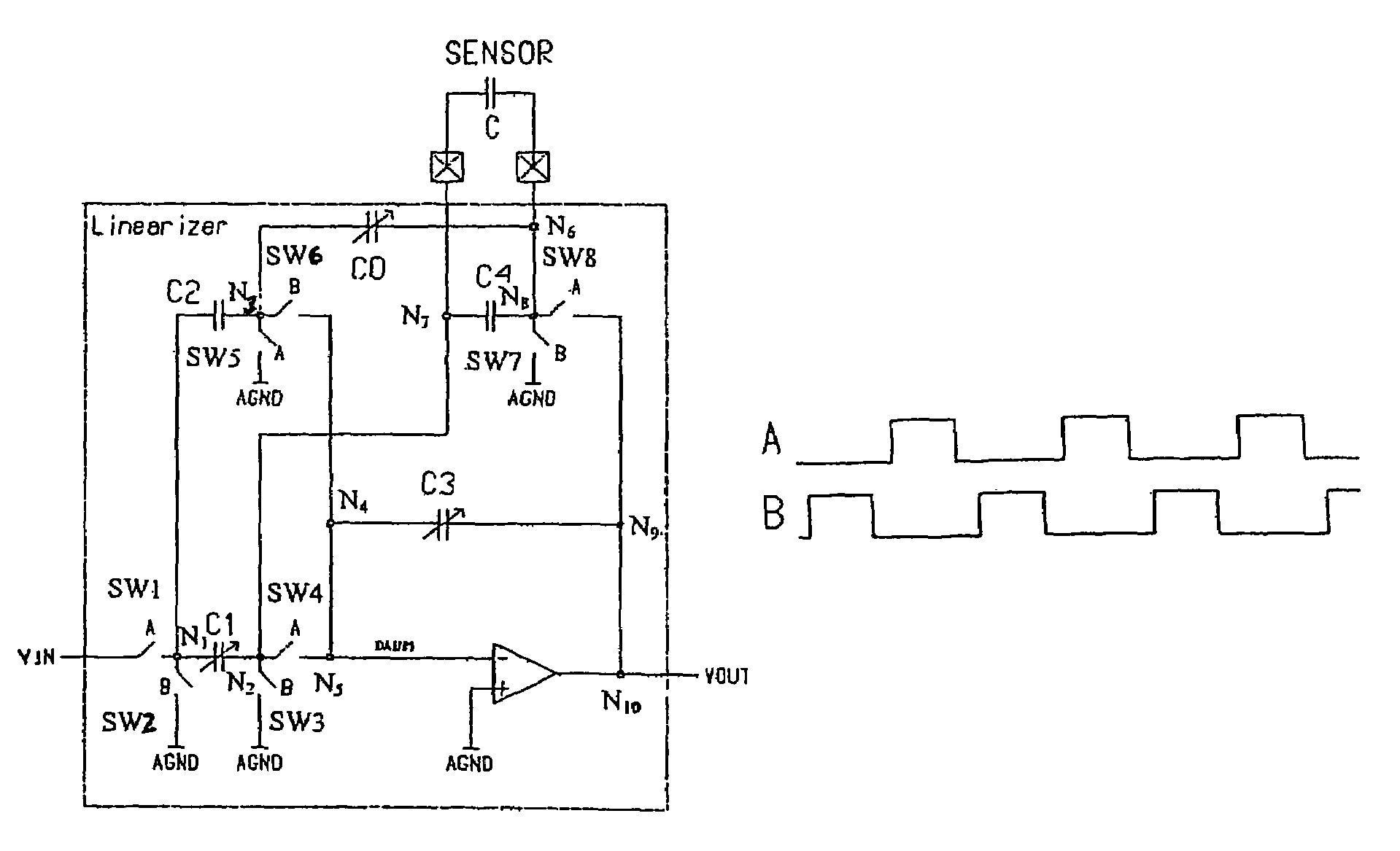
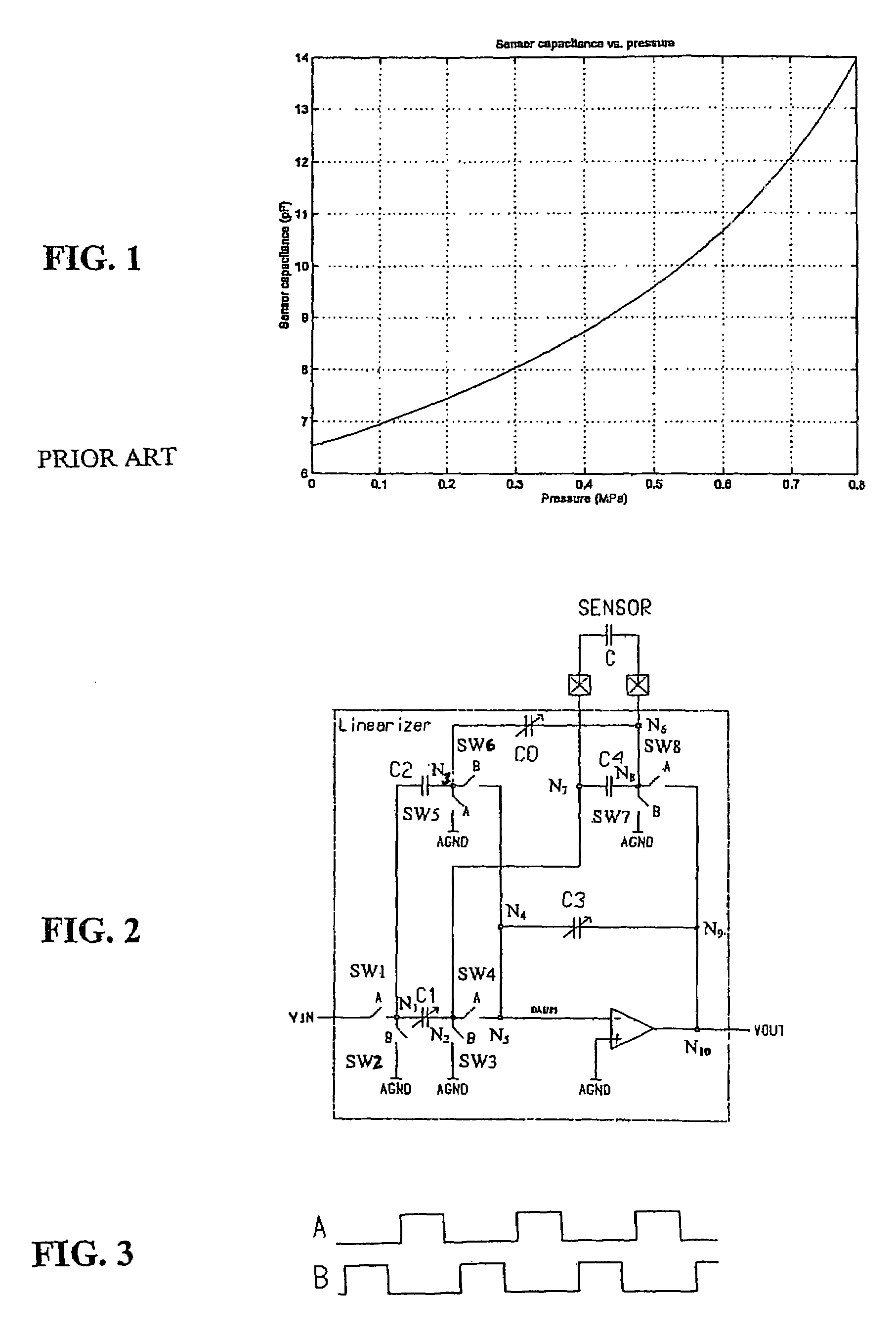
[0021]FIG. 2 is a schematic diagram of a circuit according to the present invention realizing the function of Equation 3. In FIG. 2, the linearizer circuit is constructed using only one operational amplifier A1 and five switched capacitors C0, C1, C2, C3, and C4, as well as sensor capacitance C. Switching devices SW1 to SW8 associated with the capacitors C0 to C4 are controlled by switch control signals A and B. Whenever signal A or B is active, t...


PUM

PropertyMeasurementUnit
non-linear capacitance-pressureaaaaaaaaaa
input voltageaaaaaaaaaa
chargeaaaaaaaaaa

Abstract

A linearizer circuit which corrects inherent nonlinearity of a capacitive pressure sensor is provided. The linearizer is based on an operational amplifier configuration including a feedback network of switched capacitor type that is switched between a first switching phase and a second switching phase .In this switched capacitor configuration, DC gain of the operational amplifier configuration in the second switching phase can be adapted to realize a linearization function required to substantially linearize a non-linear capacitance-pressure characteristic of a capacitive pressure sensor when the capacitive pressure sensor is connected to be part of the feedback network.

Description

FIELD OF THE INVENTION[0001]The invention relates to a linearizer circuit which corrects inherent nonlinearity of a capacitive pressure sensor.BACKGROUND OF THE INVENTION[0002]In variable capacitive transducer or capacitive pressure sensors, capacitance varies with the pressure applied to the sensor and can be detected by an appropriate electronic circuitry. A typical capacitive pressure sensor is highly nonlinear. One example of a capacitance-pressure relation is[0003]C⁡(p)=C00+kC0+C01-C0κ⁢p+aC01-C0b⁢⁢κ⁢p(1)[0004]where C00, C0, and κ are independent statistical parameters of a capacitive pressure sensor. Parameters k, a, and b are constants for a given sensor type. The applied absolute pressure is p. FIG. 1 shows a capacitance vs. pressure characteristic with parameter values C00=0.65 pF, C0=3.25 pF, κ=4180 kPa*pF, k=0, a=0.808 and b=1.410.[0005]In a pressure measurement system utilizing this kind of capacitive sensor, nonlinearity must be corrected to obtain an output signal propo...

Claims


Application Information

Patent Timeline
Patent Type & Authority Patents(United States)
IPC IPC(8): G01D18/00G01R27/00G05F1/00G01L9/12H03F
CPCG01L9/12
Inventor SIHVOLA, ESA
Owner MICRO ANALOG SYST
Learn More