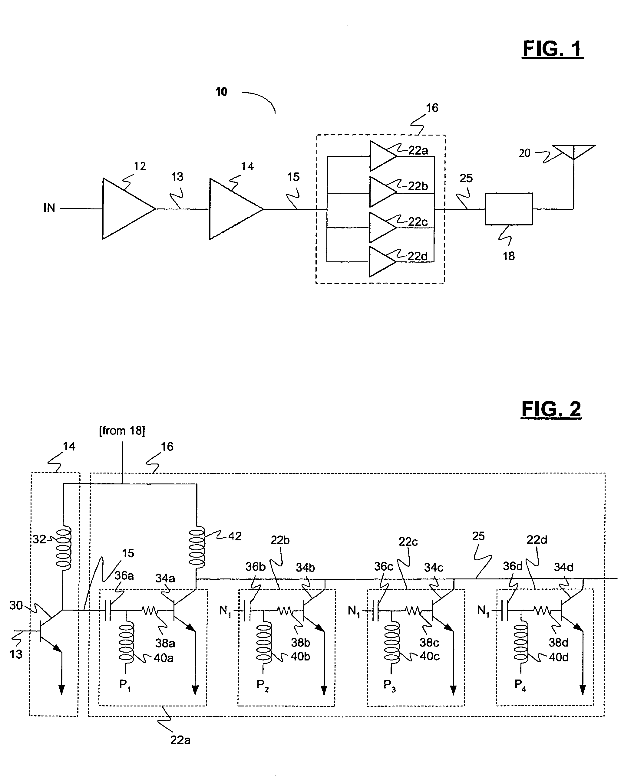
Adjustable segmented power amplifier

a power amplifier and segmented technology, applied in the field of power amplification, can solve the problems of affecting the output power range, and the size of the device generally cannot be changed, and achieve the effects of wide output power range, and large output power rang

Active Publication Date: 2008-10-28
MARVELL ASIA PTE LTD
View PDF34 Cites 48 Cited by
  • Summary
  • Abstract
  • Description
  • Claims
  • Application Information

AI Technical Summary

Benefits of technology

[0008]Embodiments of the present invention relate to adjustable, segmented amplifier circuits and architectures, systems including such an amplifier, and methods for amplifying an analog signal using such an amplifier. The circuits and / or architectures generally comprise (a) a first fixed stage configured to amplify an analog signal and provide a first amplified output at a first common node; and (b) an adjustable stage comprising a plurality of independently selectable parallel amplifier segments, each of the parallel amplifier segments having an input at the first common node and an output at a second common node, wherein the adjustable stage is configured to provide a unique high-efficiency output power range corresponding to a unique number of selected parallel amplifier segments. The systems generally comprise an integrated circuit (IC) that includes the present amplifier circuit and / or architecture embodying one or more of the inventive concepts disclosed herein. The methods generally comprise the steps of (1) amplifying the analog signal in a fixed amplifier stage, (2) selecting a number of parallel amplifier segments for subsequent signal amplification, and (3) amplifying the amplified analog signal with the activated parallel, selectable amplifier segments to generate an output signal in one of a plurality of predetermined output power ranges corresponding to the number of selected parallel amplifier segments.
[0009]The present invention advantageously provides a power amplifier that operates efficiently over a large output power range, that exhibits unconditional stability over a wide output power range, and that does not consume an inordinate amount of chip area. Furthermore, in certain preferred embodiments, the present amplifier exhibits excellent input and / or output matching and / or an insignificant and / or immaterial degree of parameter variability, regardless of the number of parallel output segments that are selected for operation. These and other advantages of the present invention will become readily apparent from the detailed description of preferred embodiments below.

Problems solved by technology

However, once the bipolar amplifier is manufactured, the size of the devices generally cannot be changed, thereby effectively preventing the same power amp from providing highly efficient low power and “normal operation” modes.
However, such an approach consumes a relatively large chip area, in comparison to single amplifier designs.
Furthermore, this approach typically introduces a digital or CMOS switch in the RF signal path, thereby introducing (i) non-linearities into the signal amplification function and / or (ii) attenuation and / or insertion loss into the signal itself.
While this approach extends the efficient range of operation, it does so at the cost of reduced linearity and potentially unacceptable linearity at the lower end of the output power range.

Method used


Image

  • Adjustable segmented power amplifier
  • Adjustable segmented power amplifier
  • Adjustable segmented power amplifier

Examples


Embodiment Construction

[0020]Reference will now be made in detail to the preferred embodiments of the invention, examples of which are illustrated in the accompanying drawings. While the invention will be described in conjunction with the preferred embodiments, it will be understood that they are not intended to limit the invention to these embodiments. On the contrary, the invention is intended to cover alternatives, modifications and equivalents, which may be included within the spirit and scope of the invention as defined by the appended claims. Furthermore, in the following detailed description of the present invention, numerous specific details are set forth in order to provide a thorough understanding of the present invention. However, it will be readily apparent to one skilled in the art that the present invention may be practiced without these specific details. In other instances, well-known methods, procedures, components, and circuits have not been described in detail so as not to unnecessarily ...


PUM


Abstract

An architecture, circuits, systems and a method for amplifying an analog signal. The architecture and/or circuit generally includes a first fixed stage (e.g., a predriver) and an adjustable stage. The first fixed stage may be configured to amplify an analog signal and provide a first amplified analog output at a first common node. The adjustable stage may comprise a plurality of independently selectable parallel amplifier segments. Each of the parallel segments may have an input at the first common node and an output at a second common node, a transistor having a control terminal, and a first inductor in electrical communication with the control terminal of the transistor. The adjustable stage may be configured to apply a bias to the control terminal of the transistor in a selected segment and to provide an output signal in one of a plurality of a power ranges corresponding to a number of selected parallel amplifier segments. The output signal generally has a minimum power efficiency when two or more of the parallel segments are selected. The present invention advantageously provides a relatively compact power amplifier with an extended output power range at which the amplifier is highly efficient. In preferred embodiments, the input and output matching characteristics are generally independent of the number of selected output amplifier segments.

Description

RELATED APPLICATIONS[0001]This application claims the benefit of U.S. Provisional Application No. 60 / 470,686, filed May 14, 2003, which is incorporated herein by reference in its entirety.FIELD OF THE INVENTION[0002]The present invention generally relates to the field of power amplification. More specifically, embodiments of the present invention pertain to an adjustable, segmented power amplifier, circuitry, architectures, and devices including such a power amplifier, and methods for operating such a power amplifier.DISCUSSION OF THE BACKGROUND[0003]Radio frequency (RF) transmitters in wireless networks are generally required to operate in a linear region of a power-vs.-gain curve. If the transmitter is used in a system over a range of transmission power, linearity is generally measured by how the output gain (e.g., the P1 dB, or 1 dB compression point with reference to the output power) scales as a function of output power. For example, as the transmitter power is lowered, the P1 ...

Claims


Application Information

Patent Timeline
Patent Type & Authority Patents(United States)
IPC IPC(8): H03G3/10H04B1/04
CPCH03F1/0261H03F1/0277H03F3/211H03F3/245H03F3/45085H03F3/602H03G1/0088H04B1/0483H03F2200/09H03F2200/18H03F2200/423H03F2200/451H03F2200/541H03F2203/21139H03F2203/21178H03F2203/45731
Inventor LOEB, WAYNETSAI, KING CHUN
Owner MARVELL ASIA PTE LTD
Why Eureka
Try Eureka