
Straddle mount connector

a connector and cable mount technology, applied in the direction of coupling device connection, coupling device details, printed circuits, etc., can solve the problems of reducing the antenna effect, requiring scrapping of entire boards, and requiring laborious and time-consuming process of making sure, so as to reduce the antenna effect and eliminate the problem

Active Publication Date: 2008-10-28
TYCO ELECTRONICS LOGISTICS AG (CH)
View PDF13 Cites 13 Cited by
  • Summary
  • Abstract
  • Description
  • Claims
  • Application Information

AI Technical Summary

Benefits of technology

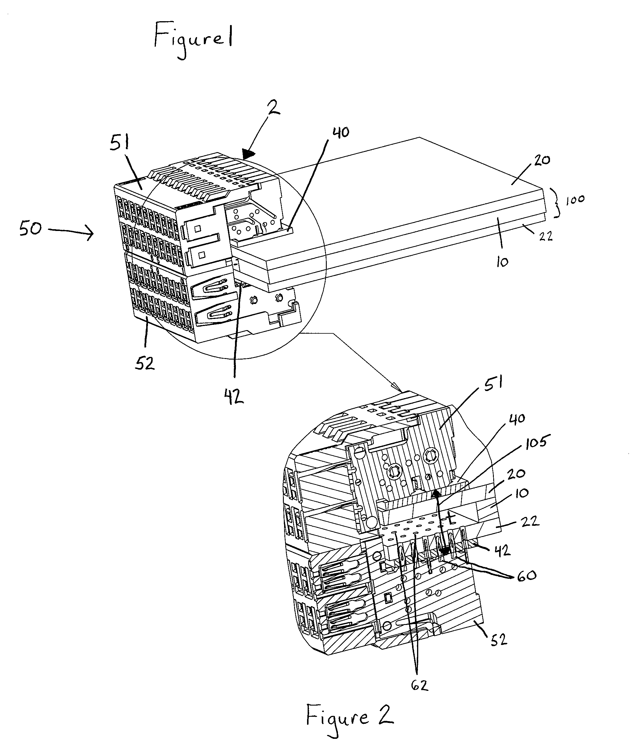
The invention is a straddle mount connector for use with a component electrical card. The connector has two rigid connector portions that matingly engage the card and an electronic device, and a fixed gap between them to accommodate cards of different thicknesses. The connector does not have tails that extend beyond the card, reducing antenna-effect and allowing for high data transfer speeds. The connector also eliminates problems associated with alignment and soldering. The invention provides a universal solution for connecting component electrical cards to electronic devices.

Problems solved by technology

Electronic equipment, such as that used in military applications, is often required to be operated in rugged, extreme environmental conditions.
Examples of such conditions include excessive moisture, salt, heat, vibration, mechanical shock, and electromagnetic interference.
The sealed container, while effective at protecting the electronic equipment, exacerbates problems associated with removal of heat generated by operating the electronic equipment because there is little or no airflow for convection cooling.
This is undesirable for a number of reasons.
This typically requires a tedious, time consuming process of making sure the connector is properly aligned with the boards.
If the soldering is off by even a little bit, one or more of the circuits on the board may be discontinuous, leaving an open circuit.
If the connector is misaligned or a circuit is damaged, the entire board, which is usually very expensive, must typically be scrapped.
As a result, the tails tend to act like antennae, creating interference that limits the speed at which the boards can operate to about 1 GB / sec or lower.
Furthermore, as antennae, they may act as transmitters of interfering signals as well as receivers that may make the circuit susceptible to jamming.
While the flex circuits may provide easier access for the soldering, similar problems of alignment are still presented.
Like the U-shaped connector, the flex circuit has long tails that act like antennae, which create interference and limits performance as described above.

Method used


Image

  • Straddle mount connector
  • Straddle mount connector
  • Straddle mount connector

Examples


Embodiment Construction

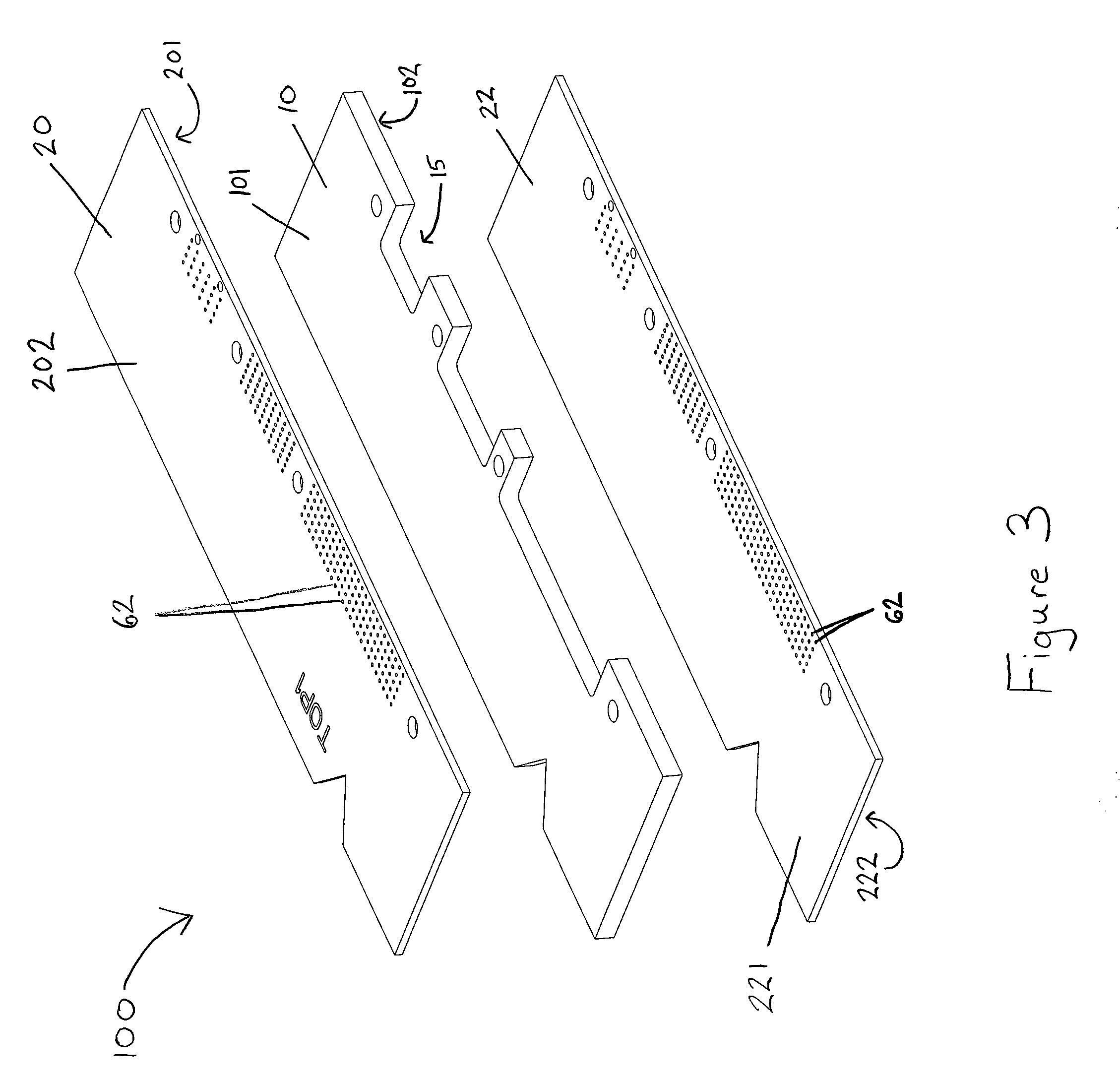
[0020]FIG. 1 illustrates a perspective view of a straddle mount connector 50 mounted on an electrical card 100 in accordance with an exemplary embodiment of the invention. The electrical card 100 comprises a heat sink member 10, a first electrical panel member 20 and a second electrical panel member 22, each of which electrical panel members are preferably printed circuit boards (PCBs). The straddle mount connector 50 comprises a first substantially rigid connector portion 51 and a second substantially rigid connector portion 52. Each connector portion 51, 52 is separately in electrical contact with a single electric panel member 20, 22 of the electrical card 100.

[0021]The heat sink member 10 may be any thermally conductive material, such as copper, gold, aluminum or composite, by way of example only. Referring to FIG. 3, the heat sink member 10 has a first surface 101 and an opposing second surface 102. The heat sink member 10 is typically of substantially uniform thickness and sub...


PUM


Abstract

A straddle mount connector for use with a computer card having multiple circuit boards on opposing sides of a heat sink is disclosed. The straddle mount connector includes a pair of connector portions on opposing sides of the computer card. A first surface of the first connector portion is in electrical and physical contact with a board on one side of the heat sink while a first surface of the second connector portion is in electrical and physical contact with the board on the other side of the surface. The first surface of the first connector portion and the first surface of the second connector portion are separated by a fixed, predetermined distance.

Description

FIELD OF THE INVENTION[0001]The present invention is directed to a connector for use in combination with electrical panel members and more particularly to a straddle mount connector for use in combination with two electrical panel members separated by a heat sink.BACKGROUND OF THE INVENTION[0002]Electronic equipment, such as that used in military applications, is often required to be operated in rugged, extreme environmental conditions. Examples of such conditions include excessive moisture, salt, heat, vibration, mechanical shock, and electromagnetic interference. To protect the generally fragile nature of the electronic equipment, the equipment is encased in sealed containers, essentially isolating the electronic equipment from the surrounding environment.[0003]The sealed container, while effective at protecting the electronic equipment, exacerbates problems associated with removal of heat generated by operating the electronic equipment because there is little or no airflow for co...

Claims


Application Information

Patent Timeline
Patent Type & Authority Patents(United States)
IPC IPC(8): H01R12/00
CPCH01R12/724H01R12/585
Inventor ROBINETTE, DALE T.
Owner TYCO ELECTRONICS LOGISTICS AG (CH)
Learn More