Vehicular crash attenuator

a technology of attenuator and vehicle, which is applied in the direction of shock absorber, elastic damper, way, etc., can solve the problems of no longer practicable to rotate the entire cartridge directly attached, and driving dangerous problems

Inactive Publication Date: 2008-10-21
TRAFFIX DEVICES INC
View PDF17 Cites 15 Cited by
  • Summary
  • Abstract
  • Description
  • Claims
  • Application Information

AI Technical Summary

Benefits of technology

[0009]The present invention overcomes the problems of the prior art, namely excessive length during use in a horizontal position, and excessive height in a vertical transport position, as well as wind resistance and buffeting at highway speeds, and limited protection for errant vehicles which impact the TMA device from an angle (i.e. “coffin corner” impact).
[0010]Other advantages of the inventive system include its simple, low cost construction, as well as its modular construction, so that only damaged portions of the TMA can be removed and replaced in the field after impact.
[0011]The inventive system utilizes a novel method of buckling outwardly curved tubular members which comprise each member of the TMA system; i.e. the strut member and the cartridge member. The rigid sides of the cartridge are buckled at a high initial force, then proceed to crush at a lower force once the sides have buckled outwardly sufficiently to protect vehicle occupants during the critical first two feet of travel after impact. The goal is to prevent the vehicle from decelerating at a rate of more than 40 ft / sec. during this critical two feet of travel.

Problems solved by technology

Such a length makes it no longer practical to rotate an entire cartridge that is directly attached to the fixed backup due to excessive height.
Because prior art TMA's employ The wind resistance of the cartridge tends to create buffeting problems, which can make driving hazardous.

Method used


Image

  • Vehicular crash attenuator
  • Vehicular crash attenuator
  • Vehicular crash attenuator

Examples


Embodiment Construction

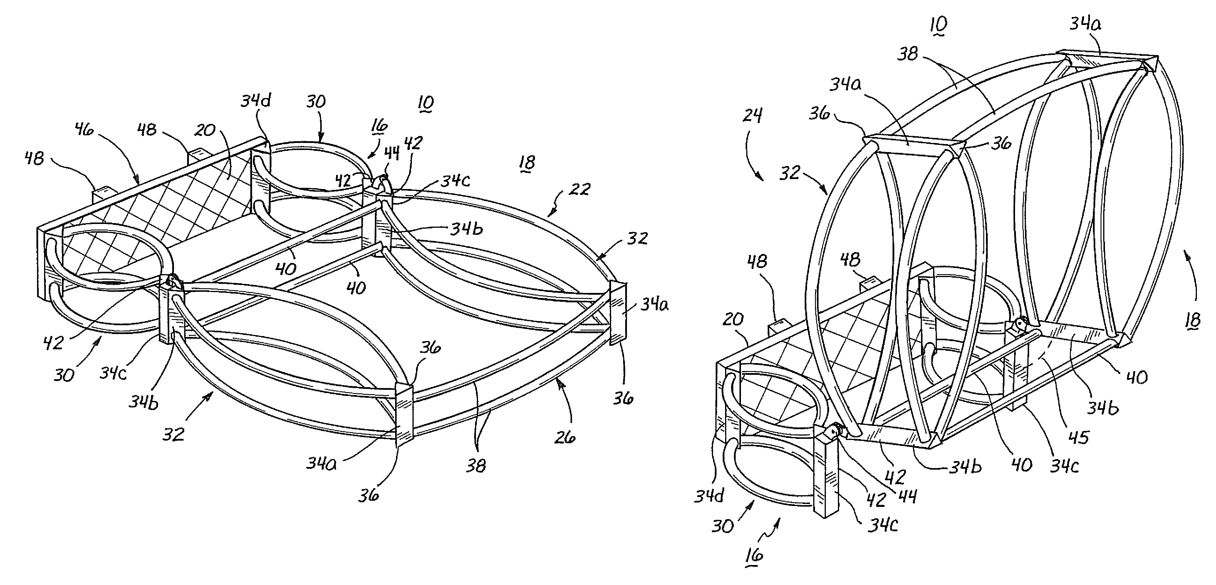
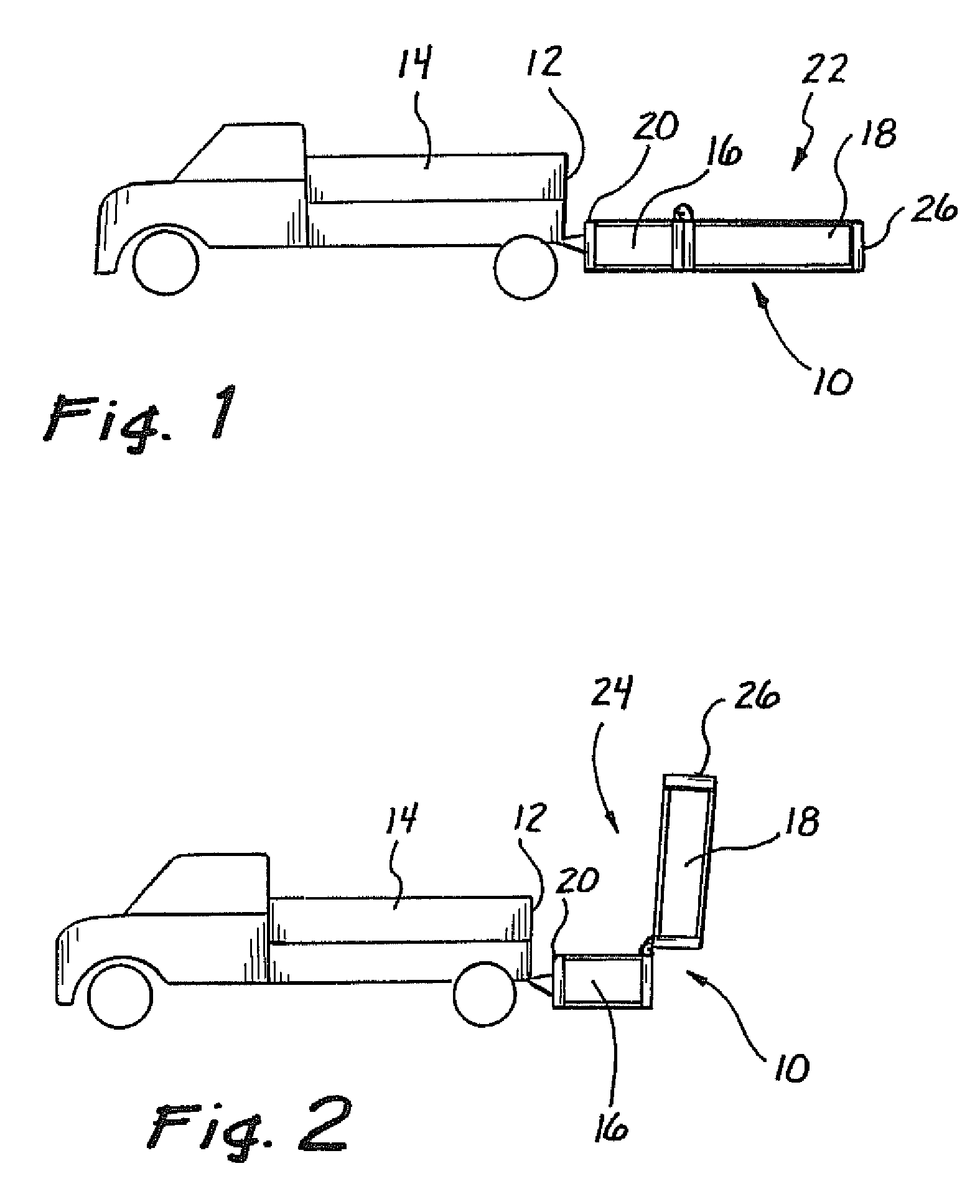
[0032]Referring now to the figures, wherein, like reference numerals refer to like elements throughout the figures, and referring specifically to FIGS. 1 and 2, a truck mounted crash attenuator (TMA) 10 is mounted to a rear end 12 of a truck 14. The TMA 10 is comprised of a strut 16 and a cartridge 18. The TMA strut 16 is attached to a backup 20 that is rigidly attached to the truck rear end 12. The TMA cartridge 18 is pivotally attached to the strut 16 and is located behind the truck 14.

[0033]As discussed below, embodiments of the invention have a reduced length compared to the prior art due to the design of the strut 16 and the cartridge 18. The energy absorbing cartridge 18 is designed to first decelerate lightweight colliding vehicles with a maximum velocity change of 40 ft / sec during the first two feet of occupant travel after impact. The distance the cartridge crushes is less if the compression force is initially high and then lower (see FIG. 9). Embodiments of the present inv...


PUM


Abstract

A truck mounted attenuator (TMA) is constructed to minimize length during use in a horizontal position and height in a vertical transport position, as well as to minimize wind resistance and buffeting at highway speeds. A modular construction is employed, so that only damaged portions of the TMA can be removed and replaced in the field after a vehicle impact. The TMA comprises a plurality of outwardly curved tubular structural members which are designed to buckle upon application to the TMA of forces resulting from vehicular impact. The rigid tubes buckle at a high initial force, then proceed to crush at a lower force once the sides have buckled outwardly sufficiently to protect vehicle occupants during the critical first two feet of travel after impact. This design also provides increased protection for errant vehicles which impact the TMA device from an angle (i.e. “coffin corner” impact).

Description

[0001]This application is a continuation under 35 U.S.C. 120 of U.S. patent application Ser. No. 11 / 364,662, filed on Feb. 27, 2006, now allowed, which is a continuation of U.S. patent application Ser. No. 11 / 136,353, filed on May 23, 2005, now abandoned, which in turn is a continuation of U.S. patent application Ser. No. 10 / 413,074, filed on Apr. 14, 2003 and now U.S. Pat. No. 6,926,324, which in turn is a continuation of U.S. patent application Ser. No. 09 / 561,480, filed on Apr. 28, 2000, and now U.S. Pat. No. 6,581,992, which in turn claimed the benefit under 35 U.S.C. 119(e) of U.S. Provisional Application Ser. No. 60 / 131,626, filed on Apr. 28, 1999. All of the above reference applications are herein expressly incorporated by reference.BACKGROUND OF THE INVENTION[0002]1. Field of the Invention[0003]This invention relates to attenuators which are particularly adapted for the absorption of energy in the event of an impact between an errant vehicle and a second, typically stationar...

Claims


Application Information

Patent Timeline
Patent Type & Authority Patents(United States)
IPC IPC(8): B60R19/18B60R19/00
CPCB60R19/00E01F15/148B60R2019/005
Inventor GERTZ, DAVID C.
Owner TRAFFIX DEVICES INC
Why Eureka
Try Eureka