
Method and system for wireless admission control based on fixed or mobile nature of wireless communication devices

a wireless communication and fixed or mobile nature technology, applied in the field of wireless communication, can solve the problems of increasing interference, unable to support further calls, and limited capacity of each wireless coverage area of a cellular wireless communication system, so as to reduce interference, reduce call quality, and limit capacity

Active Publication Date: 2008-10-14
SPRING SPECTRUM LP
View PDF11 Cites 17 Cited by
  • Summary
  • Abstract
  • Description
  • Claims
  • Application Information

AI Technical Summary

Benefits of technology

[0015]Generally speaking, each wireless coverage area in a cellular wireless communication system has limited capacity. Depending on the protocol used for communication, this capacity limit can take various forms. In a code division multiple access (CDMA) system, for example, each sector may have a limited number of coded traffic channels for carrying calls over the air interface. Once all of those channels are in use, the sector may be unable to support further calls. Further, as a RAN allows more calls to proceed simultaneously in a given sector, each call may experience increased interference and therefore reduced call quality.
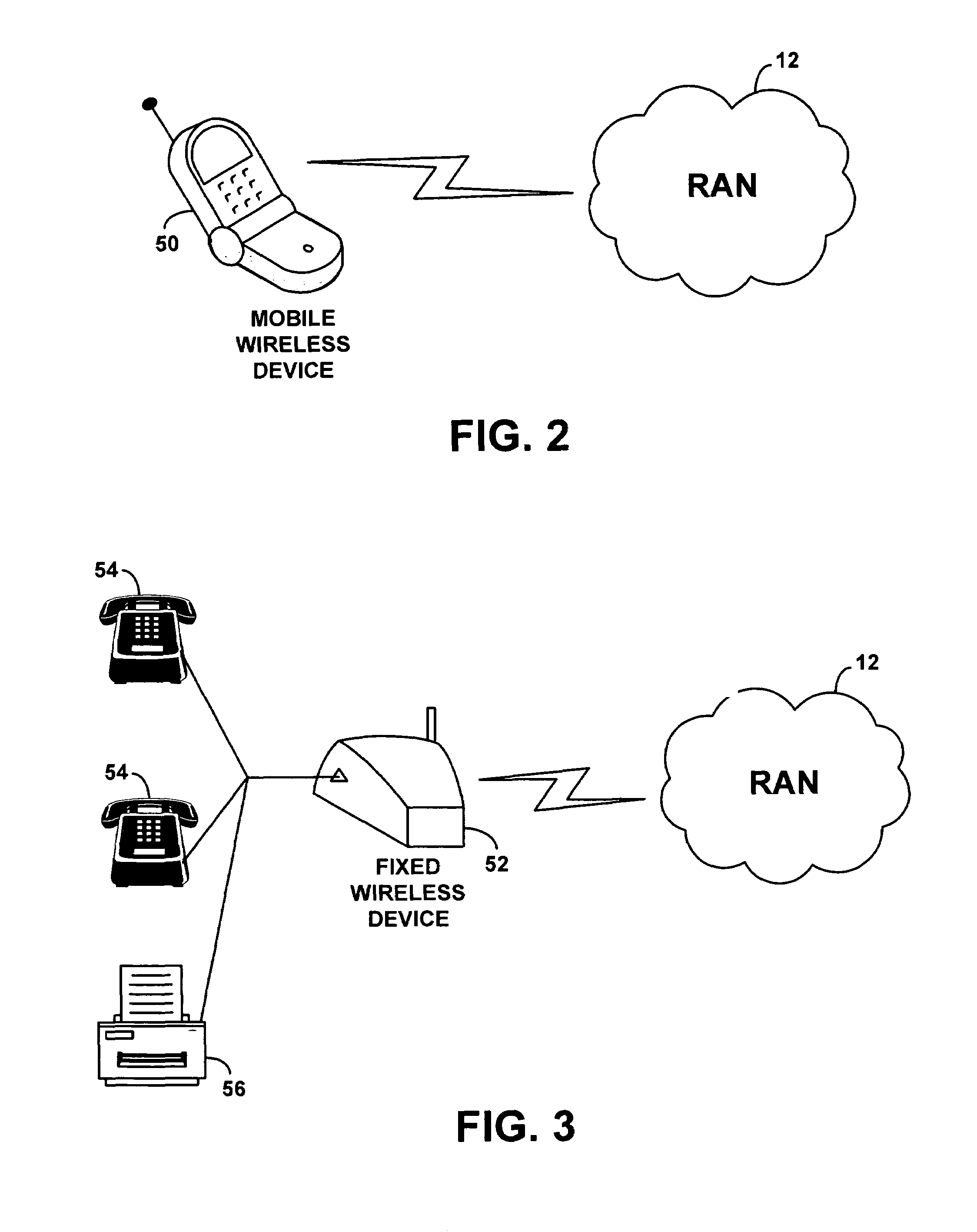
[0018]Giving higher admission priority to fixed wireless calls as compared with mobile wireless calls could provide more consistent, predictable service for fixed wireless calls than for mobile wireless calls. This may, in turn, benefit users of fixed wireless devices, who expect their wireless service to emulate landline telephone service, and therefore to be free from blocks, drops and interference that might arise from overloading in their wireless coverage area. On the other hand, there may be reason in certain situations to give higher admission priority to calls involving mobile wireless devices than to calls involving fixed wireless devices.

Problems solved by technology

Generally speaking, each wireless coverage area in a cellular wireless communication system has limited capacity.
Once all of those channels are in use, the sector may be unable to support further calls.
Further, as a RAN allows more calls to proceed simultaneously in a given sector, each call may experience increased interference and therefore reduced call quality.

Method used


Image

  • Method and system for wireless admission control based on fixed or mobile nature of wireless communication devices
  • Method and system for wireless admission control based on fixed or mobile nature of wireless communication devices
  • Method and system for wireless admission control based on fixed or mobile nature of wireless communication devices

Examples


Embodiment Construction

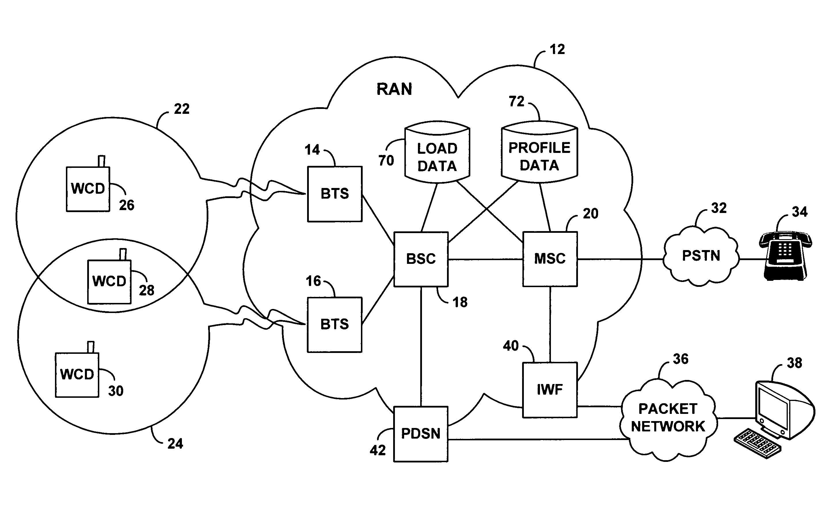
[0038]Referring to the drawings, FIG. 1 is a block diagram of an example cellular wireless communication system arranged to carry out an embodiment of the invention. As shown, the example system includes at its core a radio access network (RAN) 12 comprising two base transceiver stations (BTSs) 14, 16, one base station controller (BSC) 18, and one mobile switching center (MSC) 20. As noted above, these RAN entities are functional in nature and can be integrated and distributed in various ways. Further, a RAN could alternatively include more or fewer of the entities shown or could include other entities or take some other form altogether.

[0039]Conventionally, each BTS may comprise an antenna tower (not shown) that radiates to define one or more wireless coverage areas in which wireless communication devices (WCDs) can operate. By way of example, FIG. 1 shows BTS 14 radiating to define a first wireless coverage area 22, and BTS 16 radiating to define a second wireless coverage area 24...


PUM


Abstract

A method and system for wireless admission control. The system monitors the air interface load in various wireless coverage areas, such as sectors for instance. When the load exceeds a designated level, the system begins making call admission decisions based on whether the calls involve mobile wireless devices (such as handheld cell phones) or fixed wireless devices (such as wall-mounted cell phones or wireless local loop hubs). Further, the system may additionally base its admission decisions on the type of bearer traffic carried by the calls, such as whether the calls carry voice, fax or data traffic.

Description

BACKGROUND OF THE INVENTION[0001]1. Field of the Invention[0002]The present invention relates to wireless communications and, more particularly, to distribution of call load among coverage areas in a cellular wireless communication system.[0003]2. Description of Related Art[0004]In a typical cellular wireless communication system, an area is divided geographically into a number of cell sites, each defined by a radio frequency (RF) radiation pattern from a respective base transceiver station (BTS) antenna. The base station antennae in the cells are in turn coupled with a base station controller (BSC), which is then coupled with a switch or gateway that provides connectivity with a transport network such as the public switched telephone network (PSTN) or the Internet. For instance, the BSC may be coupled with a mobile switching center (MSC) that provides connectivity with the PSTN and / or the BSC may be coupled with a packet gateway, such as a packet data serving node (PDSN) or media g...

Claims


Application Information

Patent Timeline
Patent Type & Authority Patents(United States)
IPC IPC(8): H04Q7/20H04W28/16H04W36/30H04W36/38H04W48/06H04W76/04
CPCH04W28/16H04W48/06H04W76/04H04W36/30H04W36/38H04W76/20H04W36/302
Inventor SATAPATHY, DURGA P.
Owner SPRING SPECTRUM LP
Learn More