
Resilient packet ring network for realizing MAC bridging

a packet ring network and resilient technology, applied in the field of ring networks, can solve the problems of bridge system, large load in terms of cost and speed, and standard forwarding methods that have not yet taken shap

Inactive Publication Date: 2008-10-14
FUJITSU LTD
View PDF7 Cites 17 Cited by
  • Summary
  • Abstract
  • Description
  • Claims
  • Application Information

AI Technical Summary

Benefits of technology

The invention provides a technology for a RPR network that eliminates the need for a distinguishing flag or special ET to indicate that a MAC frame is encapsulated. This is achieved by allowing station nodes and bridge nodes to capture and encapsulate MAC frames without needing to set a destination address. The invention also allows for the efficient transmission of MAC frames without the need for a distinguishing flag or special ET. Additionally, the invention provides a compatibility with existing RPR nodes by allowing each of the station nodes and bridge nodes to have a table registered with the MAC addresses of all the other nodes connected to the rings.

Problems solved by technology

The proposed method also, however, has a problem, and, in the present, standards of the forwarding method are not yet taken shape.
In the case of the same layer protocol as the RPR where the frame dealt with by the off-the-ring station is an Ethernet frame, etc., however, there is a large load in terms of a cost and a speed.
The transparent bridge system has, however, some problems that will be given as follows.
Therefore, in the bridge node through which the frame addressed to the off-the-ring device is passed, the frame is copied addressed to the network connected to the bridge nodes (which is called blooding), and there is a possibility of increasing the load on the network.
The bridge nodes BL, BC are, however, unable to learn.
However, the intermediate bridge nodes BL, BC, BF and BI cannot ever learn the address of the frame passing through the nodes themselves, resulting in a constant occurrence of the blooding (see FIG. 24: for example, Non-Patent document 8, slides 11 and 12).
In other words, the load on the network rises.
Thus, the transparent bridge system in the present situation has a possibility that an extra load increases in some cases.
The bridge node BC, however, simply judges that the communications with the station SY fall into a failure, and there is no method of knowing that the bridge node BD can surrogate.
The use of the communication bands of almost all the nodes for a certain frame, however, conduces to a loss of Spatial Reuse (a reuse of a space) that is greatly characteristic of the RPR.
Therefore, a problem occurs afresh, wherein the meaning of utilizing the RPR is lost.
These problems are derived from the RPR MAC header destination address becoming none of the addresses of the nodes on the ring because of transmitting the frame transparently.
Therefore, a device manufactured base don the plan-A is impossible of communicating with the existing device.
This implies that an existing LSI for the RPR MAC layer processing that has been designed for the RPR device, cannot be used.
This kind of process is futile as far as the communications between the on-the-ring station nodes are concerned.
Moreover, the format related to the plan-A has such an aspect that the overhead is always large and data communication efficiency is poor.
Hence, there is no compatibility with the device manufactured based on the existing specifications, and the existing RPR MAC layer LSI can not be used.

Method used


Image

  • Resilient packet ring network for realizing MAC bridging
  • Resilient packet ring network for realizing MAC bridging
  • Resilient packet ring network for realizing MAC bridging

Examples


embodiment

[0189]FIG. 3 is a diagram showing an IP network model by way of an embodiment of the invention. FIG. 4 is an IP / MAC address table on each device (the RPR node) in the embodiment. FIG. 5 is a diagram showing an example of the topology map table retained on each RPR node shown in FIG. 3.

[0190]

[0191]At first, an outline of the network system in the embodiment will be explained. In FIG. 3, devices RA, RB, BC, BD, RE, BF are RPR nodes, and the RPR nodes are constructed of station nodes RA, RB, RE having a function as a router, and of bridge nodes BC, BC, BF having a function as a bridge. These six pieces of RPR nodes configure one ring network. Each of these RPR nodes, through transferring and receiving a topology discovery packet, has already structured the topology map table shown in the table in FIG. 5 inwardly of the device.

[0192]S1-S6 shown in FIG. 3 are stations residing outside (off the ring) the RPRT network and capable of transmitting and receiving the IP frame. These stations S...

operational example

[0194]Next, an operational example of the network system in the embodiment will be described. In the network illustrated in FIG. 3, the operational example in data transmission / receipt (A) and (B) shown as below, will be explained.

[0195](A) Data Transmission to Station S6 from Station S1

[0196]FIG. 6 is an explanatory diagram of an ARP frame format between stations S1 and S6. FIG. 7 is an explanatory diagram of a format of an IP data packet transferred and received between the stations S1 and S6.

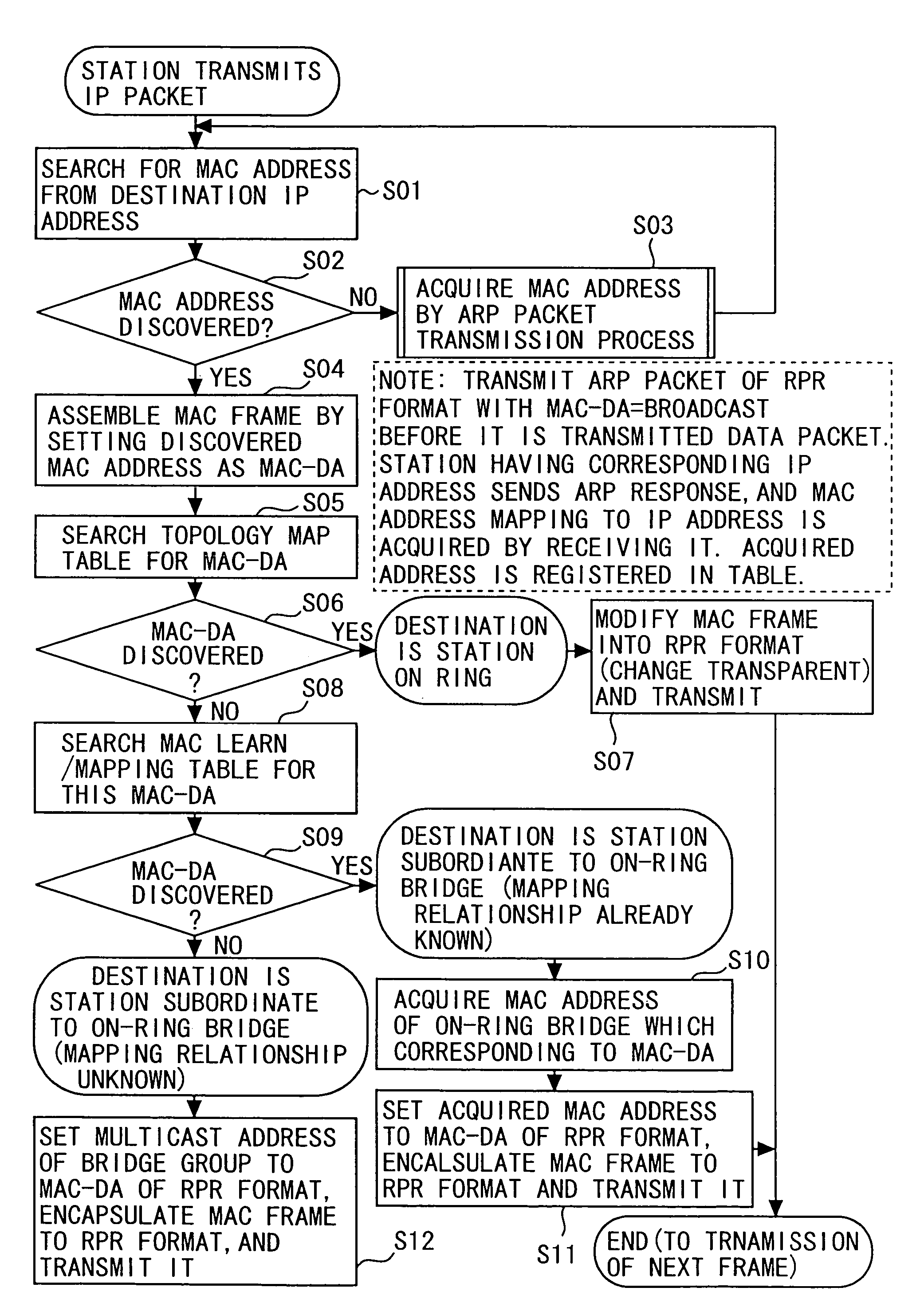
[0197]In the case of transmitting the IP data frame to the station S6 from the station S1, to begin with, the station S1 is required to know the MAC address of the station S6. Therefore, an ARP (Address Resolution Protocol) packet is sent to the network, and the MAC address of the station S6 is acquired. A frame format of the ARP packet is shown in FIG. 6.

[0198]A destination address of the frame (the ARP frame: see FIG. 6A) transmitted from the station S1 is broadcast (DA=BC). Therefore, a tr...


PUM


Abstract

A bridge node converts a MAC frame addressed to a station node into a RPR MAC frame and thus transmits it, and encapsulates a MAC frame addressed a station being located the outside of a ring and connected to other bridge node into the RPR MAC frame, and transmits it. The bridge node thereby receives a RPR MAC frame into which the MAC frame is encapsulated, and the station node receives the RPR MAC frame that the MAC frame is not encapsulated.

Description

BACKGROUND OF THE INVENTION[0001]The invention relates to a ring network, and particularly to a system and an implementation technology for actualizing MAC (media access control) bridging on RPR (Resilient Packet Ring) protocol mainly defined by IEEE802.17.[0002]The RPR is a network protocol technology mainly aiming at being provided a network for connecting between cities, such as MAN / WAN (Metropolitan Area Network / Wide Area Network). An examination of the RPR is underway in order to establish a draft at the IEEE802.17 Committee. As of September in 2002, Draft version 1.0 (tentative specifications) as first standard specifications were released, at which stage they were approved at the meeting at the end of September, and the final specifications are scheduled to be determined in March in 2003 through necessary modifications thereafter. The RPR is based on SRP (Spatial Reuse Protocol) released by Cisco Corp. and has the following features.[0003]1. The RPR supports a bidirectional d...

Claims


Application Information

Patent Timeline
Patent Type & Authority Patents(United States)
IPC IPC(8): H04L12/28G06F15/16H04L12/42H04L12/46
CPCH04L12/42H04L12/4625H04L45/16
Inventor HASHIMOTO, MASANORI
Owner FUJITSU LTD
Learn More