
Image processor

a technology of image processing and image data, applied in the field of image processing, can solve the problems of image degradation, original image data to a reduction process, and takes time to achieve, and achieve the effect of smooth image display

Inactive Publication Date: 2008-10-14
FUJIFILM CORP
View PDF11 Cites 5 Cited by
  • Summary
  • Abstract
  • Description
  • Claims
  • Application Information

AI Technical Summary

Benefits of technology

[0034]With a structure of items (1) and (8), the display image data is generated through a reduction process, favorably providing the display with images high in quality.
[0035]With a structure of items (3) and (10), any image data having the highest reduction ratio is reduced. Accordingly, image processing can be done at higher speed.
[0036]With a structure of items (5) and (12), the storage can be efficiently utilized.
[0038]With a structure of items (7) and (14), the reduced image is changed in pattern responding to the movement of the display area. Accordingly, even if the display area is moved, image display can be smoothly done.

Problems solved by technology

The problem with the above types of digital cameras is that, however, every time an instruction comes for image enlargement or reduction, there needs to subject the original image data to a reduction process.
Thus, it takes time therefor.
The problem here is that, however, for image enlargement therewith, the reduced image data is the one to be enlarged, unfavorably leading to image degradation.

Method used


Image

  • Image processor
  • Image processor
  • Image processor

Examples


first embodiment

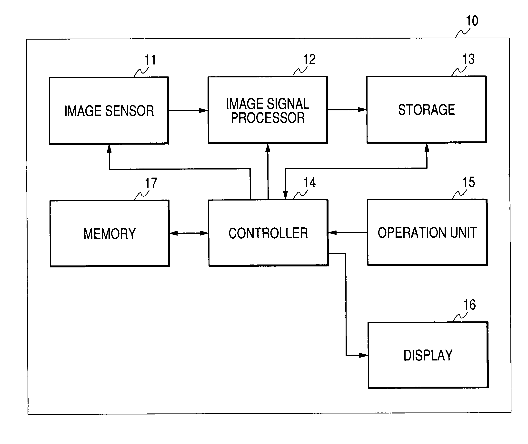
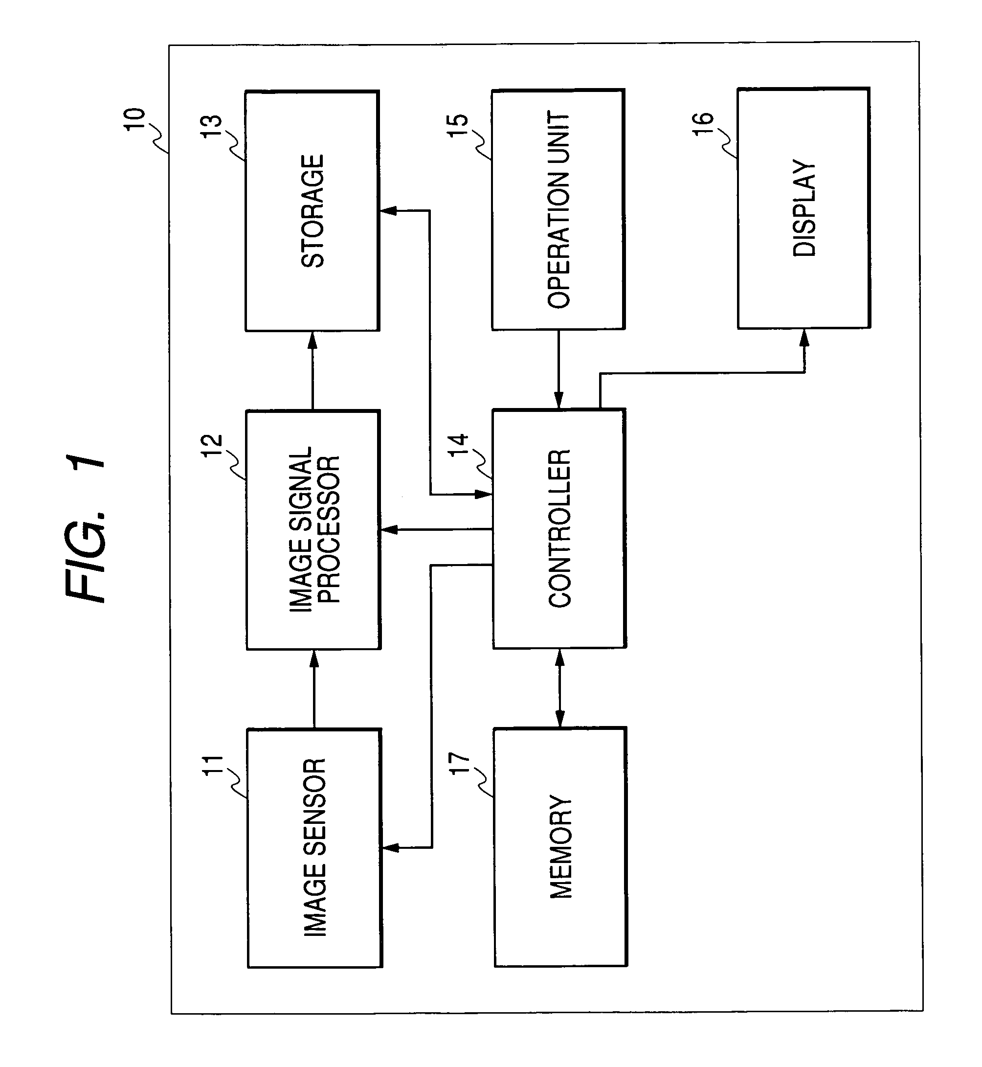
[0047]FIG. 1 is a diagram showing the schematic structure of a digital camera for illustrating a first embodiment of the present invention.

[0048]A digital camera 10 is provided with an image sensor 11 (e.g. image pick-up device or image capturing device), an image signal processor 12, a storage 13, a controller 14, an operation unit 15, a display 16, and memory 17.

[0049]The image sensor 11 includes a lens, a CCD (Charge-Coupled Device), or other device as would be envisioned by one skilled in the art, for sensing an object image. The sensed image is input to the image signal processor 12, in which image data provided by the image sensor 11 is compressed, for example. Thus processed image data (in the below, this image data is also referred to as original image data) is stored in the storage 13. The storage 13 is the one for storing the original image data.

[0050]The controller 14 is the one for controlling the digital camera 10, and includes a processor that operates based on a prede...

second embodiment

[0081]FIG. 4 is a diagram showing the schematic structure of a digital camera 40 for illustrating a second embodiment of the present invention. Herein, any component identical to that of FIG. 1 is provided with the same reference numeral for description.

[0082]The digital camera 40 is provided with the image sensor 11, the image signal processor 12, the storage 13, a controller 44, the operation unit 15, the display 16, and memory 47.

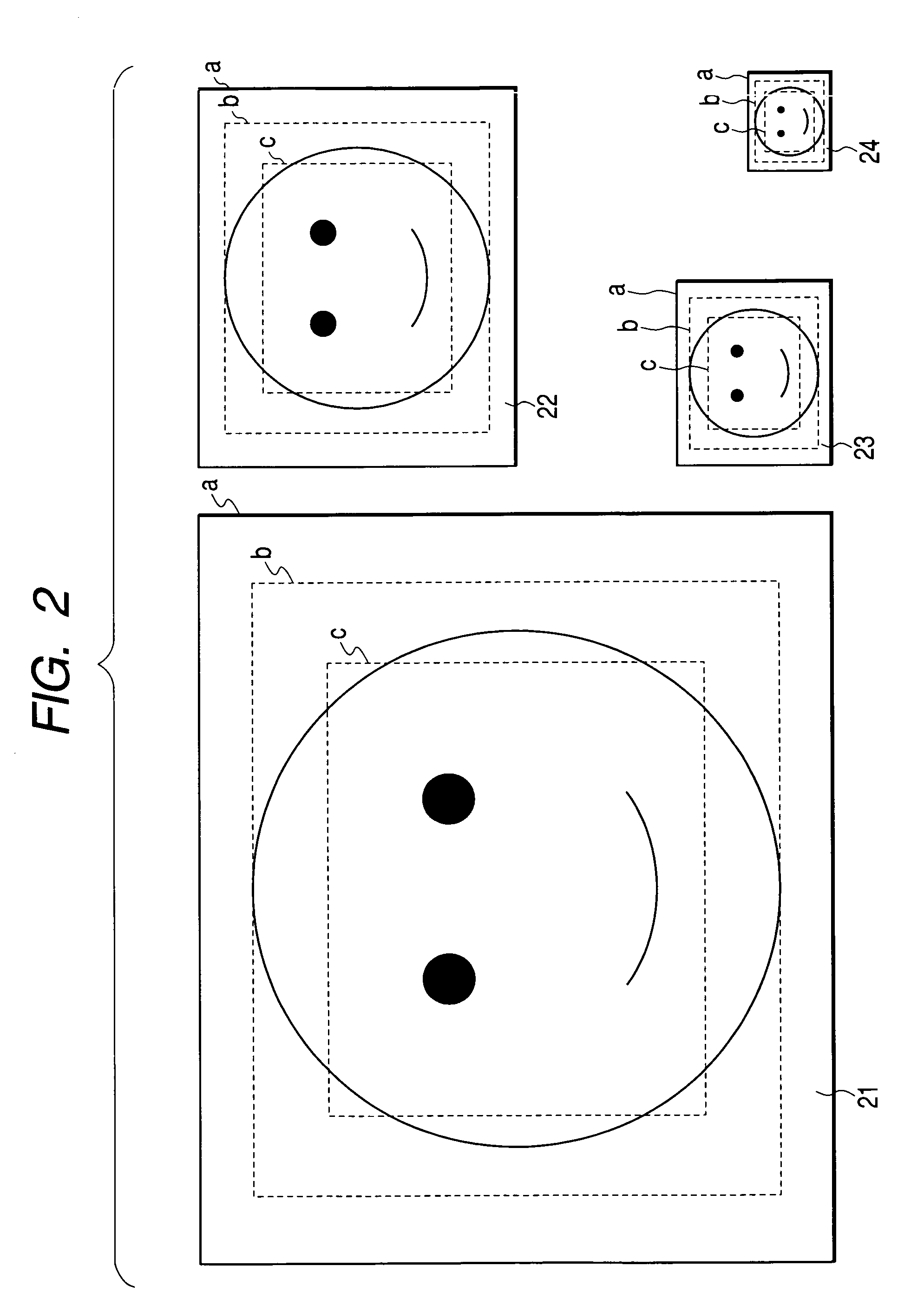
[0083]The controller 44 is the one for controlling over the digital camera 40, and is mainly structured by a processor that operates based on a predetermined program. The controller 44 reads original image data stored in the storage 13 to the memory 47. From the original image data, generated are a plurality of reduced image groups each having a different reduction ratio. Herein, the reduced image group is the one including a plurality of pieces of reduced image data all sharing the same reduction ratio but varying in pattern. Thus generated reduced imag...


PUM


Abstract

A control section of a digital camera generates a plurality of pieces of reduced image data having each different reduction ratio from original image data at the time of image viewing. The result is stored in a memory. When receiving a user instruction for reduction up an image to be displayed on a display section, the control section selects from the memory either the original image data or a plurality of reduced image data stored therein based on an image enlargement ratio and the size of display image data for output to the display section. Then, thus selected image data is subjected to a reduction process so that the display image data is generated. The resulting display image data is provided to the display section.

Description

[0001]This Nonprovisional application claims priority under 35 U.S.C. §119(a) on Patent Application No(s) 2003-134494, filed in JAPAN on May 13, 2003, the entire contents of which are hereby incorporated by reference.FIELD OF THE INVENTION[0002]The present invention relates to an image processor for processing images for display on a display.BACKGROUND OF THE INVENTION[0003]With a digital camera of a general type, a display exemplified by a display can show the result of image processing that is executed for image reducing or enlarging at the time of still image viewing. In such a case, in response to every instruction of image reduction or enlargement, the digital camera applies a reduction process and an enlargement process to original image data to display the result on the display.[0004]Alternatively, another type of a device has been proposed. That is, original image data is in advance reduced for storage as reduced image. In accordance with an image scaling ratio, a selection ...

Claims


Application Information

Patent Timeline
Patent Type & Authority Patents(United States)
IPC IPC(8): H04N1/40G06T3/40G06F3/14G09G5/36H04N1/21H04N1/393H04N5/222H04N5/225H04N5/91
CPCH04N1/393
Inventor TANAKA, SEIJI
Owner FUJIFILM CORP
Learn More